
Vehicle control device and control method

A technology for control devices and vehicles, which is applied to fluid pressure actuation devices, servo motors, servo meter circuits, etc., and can solve problems such as motor overspeed and motor damage.

Active Publication Date: 2018-06-19
GUIZHOU JONYANG KINETICS
View PDF8 Cites 0 Cited by
  • Summary
  • Abstract
  • Description
  • Claims
  • Application Information

AI Technical Summary

Problems solved by technology

When the vehicle goes downhill or the vehicle skids, the motor is prone to overspeed, and it is in the gap work area or overspeed work area. If it is in the overspeed work area or intermittent work area for more than 6 seconds, the motor may be damaged

Method used


Image

  • Vehicle control device and control method
  • Vehicle control device and control method
  • Vehicle control device and control method

Examples


Embodiment Construction

[0042] Specific embodiments of the present invention will be described in detail below in conjunction with the accompanying drawings. It should be understood that the specific embodiments described here are only used to illustrate and explain the present invention, and are not intended to limit the present invention.

[0043] The hydraulic system with single pump and dual motors is taken as an example below. It should be noted that the control device and control method are also applicable to hydraulic systems with single pump and single motor, single pump with multiple motors, and multiple pumps with multiple motors. The attached drawings are only for illustration , does not constitute a limitation to this application.

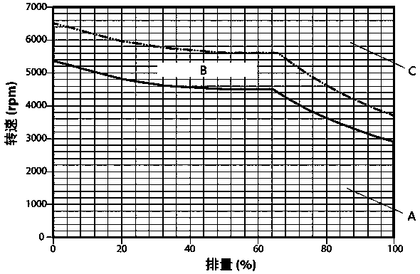
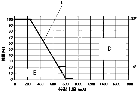
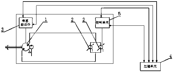
[0044] Please refer to Figure 1 to Figure 3 , figure 1 is the speed limit curve of the hydraulic motor; figure 2 is the motor displacement control curve diagram of the hydraulic motor; image 3 It is a hydraulic principle diagram of a specific embodiment...


PUM


Abstract

The invention discloses a control device for a vehicle. The control device for the vehicle comprises a sensor assembly, a processing unit and a control unit. The vehicle comprises at least one driving circuit, and the driving circuit comprises a hydraulic pump and at least one hydraulic motor. The sensor assembly comprises a rotary speed sensor, a first pressure sensor and a second pressure sensor. The rotary speed sensor is used for detecting the actual rotary speed of the hydraulic motors. The first pressure sensor is used for detecting the oil supply pressure when the hydraulic pump rotates forwards. The second pressure sensor is used for detecting the oil return pressure when the hydraulic pump rotates forwards. The processing unit is used for obtaining a parameter value according to signals collected by the sensor assembly and generating a control instruction according to the parameter value. The control unit is used for adjusting the control current of the hydraulic motor according to the control instruction. The control device is used for adjusting the work conditions of the hydraulic motors according to the actual work conditions in the driving circuit of the vehicle, guarantees that the hydraulic motors are within a normal continuous work range, and improves the use performance of the hydraulic motors. The invention further discloses a control method for the vehicle.

Description

technical field [0001] The present invention relates to the technical field of engineering machinery, in particular to a vehicle control device and control method. Background technique [0002] Construction machinery is an important part of the equipment industry, mainly used in national defense construction projects, transportation construction, energy industry construction and production, mining and other raw material industry construction and production, agriculture, forestry and water conservancy construction, industrial and civil construction, urban construction, environmental protection, etc. field. [0003] At present, the high-speed walking system mostly adopts a closed system, which is composed of a hydraulic pump and a hydraulic motor. The hydraulic pump generally adopts a two-way variable pump, and the hydraulic motor is a variable motor. The displacement of the hydraulic pump and the hydraulic motor is controlled by the current value of the proportional solenoid ...

Claims


Application Information

Patent Timeline
Patent Type & Authority Patents(China)
IPC IPC(8): F15B11/08F15B11/16F15B13/16
CPCF15B11/08F15B11/16F15B13/16F15B2211/25
Inventor 高山铁李林韩波陈伟
Owner GUIZHOU JONYANG KINETICS
Learn More