Lubrication system for a dry sump internal combustion engine

a technology of internal combustion engine and lubrication system, which is applied in the direction of closed-circuit pressure lubricating system, lubrication of auxiliaries, pressure lubrication with lubrication pump, etc., can solve the problems cooler oil, and general difficulty in withdrawing oil from the lubrication system of dry sump engin

Active Publication Date: 2013-06-18
BRP ROTAX
View PDF9 Cites 11 Cited by
  • Summary
  • Abstract
  • Description
  • Claims
  • Application Information

AI Technical Summary

Problems solved by technology

Furthermore, increased oil capacity by using a larger reservoir typically leads to cooler oil.
Dry sump engines, are, however, not without their drawbacks.
On the downside, it is generally difficult to withdraw oil from the lubrication system of a dry sump engine—e.g. for maintenance purposes (to change the oil)—as the oil does not all simply collect in an oil pan by gravity.
It is known, however, that not all such persons want to go to the effort of opening multiple oil plugs and / or of using auxiliary draining devices (e.g. suction tubes) to drain the oil from the engine.
As a result, in many cases a significant amount of used oil remains in the system after an oil change of a dry sump.
This leads to inferior quality of the oil and increased wear of engine components.

Method used


Image

  • Lubrication system for a dry sump internal combustion engine
  • Lubrication system for a dry sump internal combustion engine
  • Lubrication system for a dry sump internal combustion engine

Examples


Embodiment Construction

[0067]Although the engine of the present invention is being described herein as being usable in a personal watercraft or a snowmobile, it should be understood that it would also be possible to use this engine in other applications, such as, for example, all-terrain vehicles and motorcycles.

[0068]Throughout the detailed description and drawings, similar components will be labelled with a reference numeral followed by a letter (for example 106A, 106B). For simplicity, these similar components will be referred to by their reference numeral only when referring to the components in general and the reference numeral and the letter will be used when reference to a specific one of the similar components is being made.

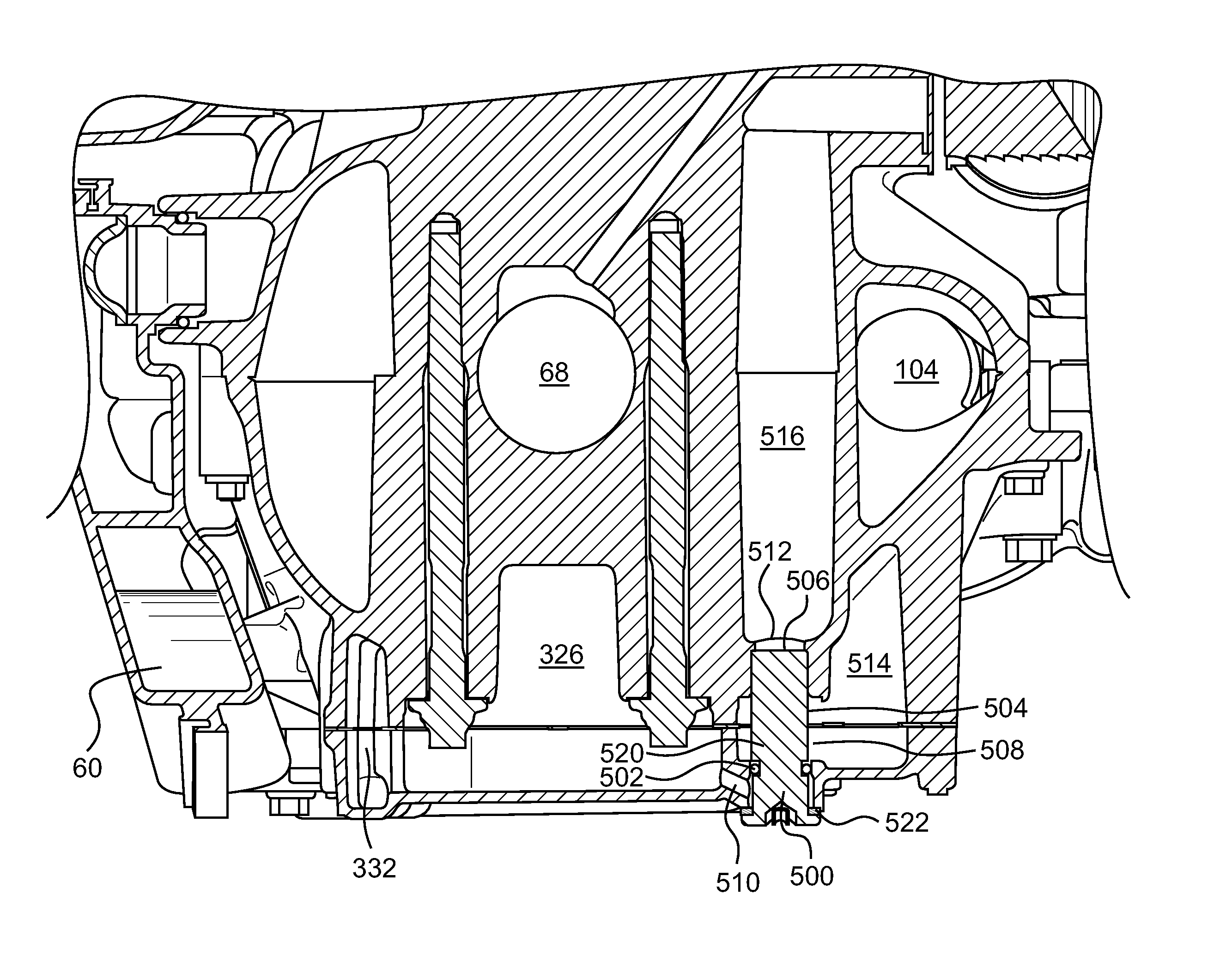
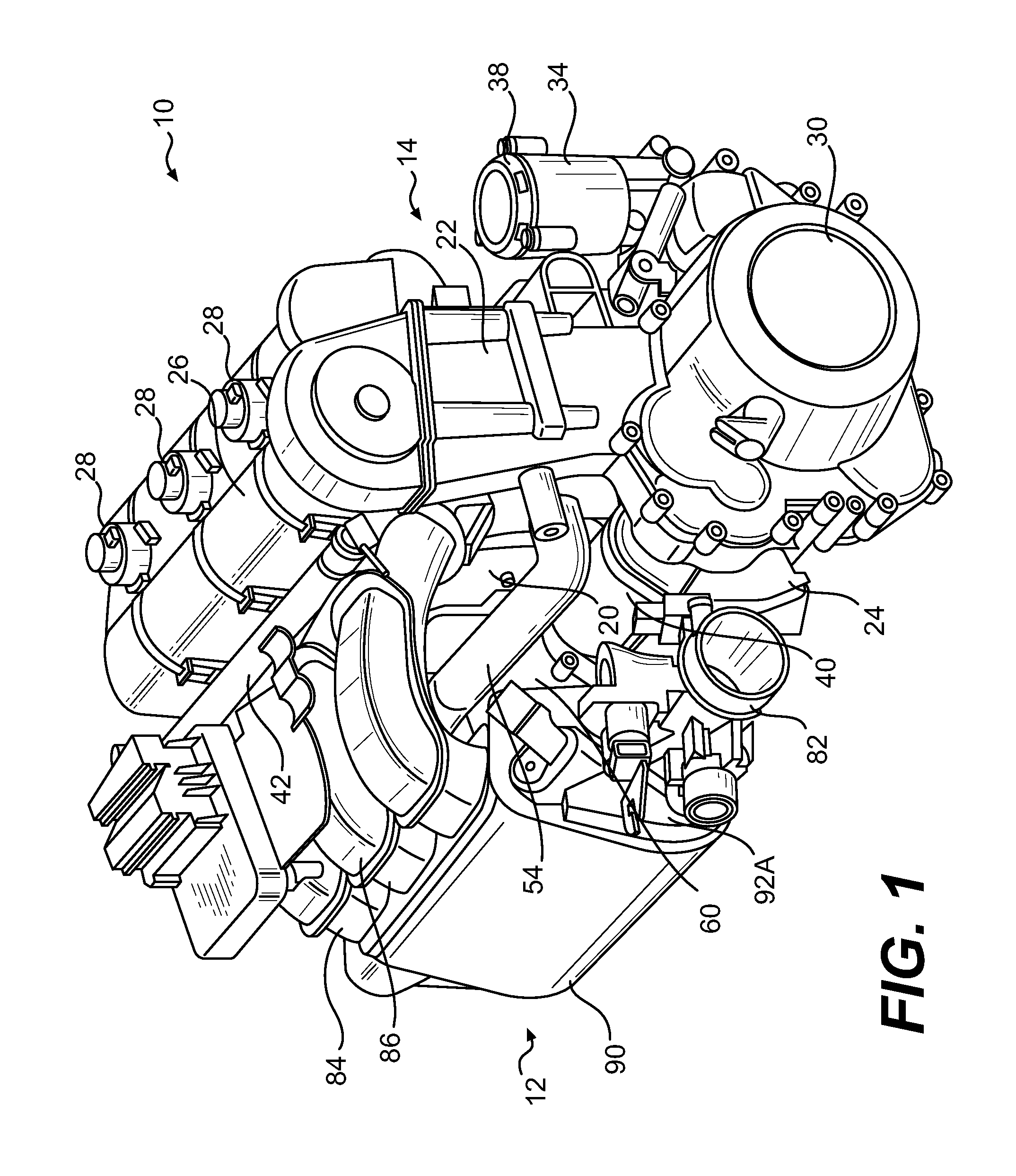
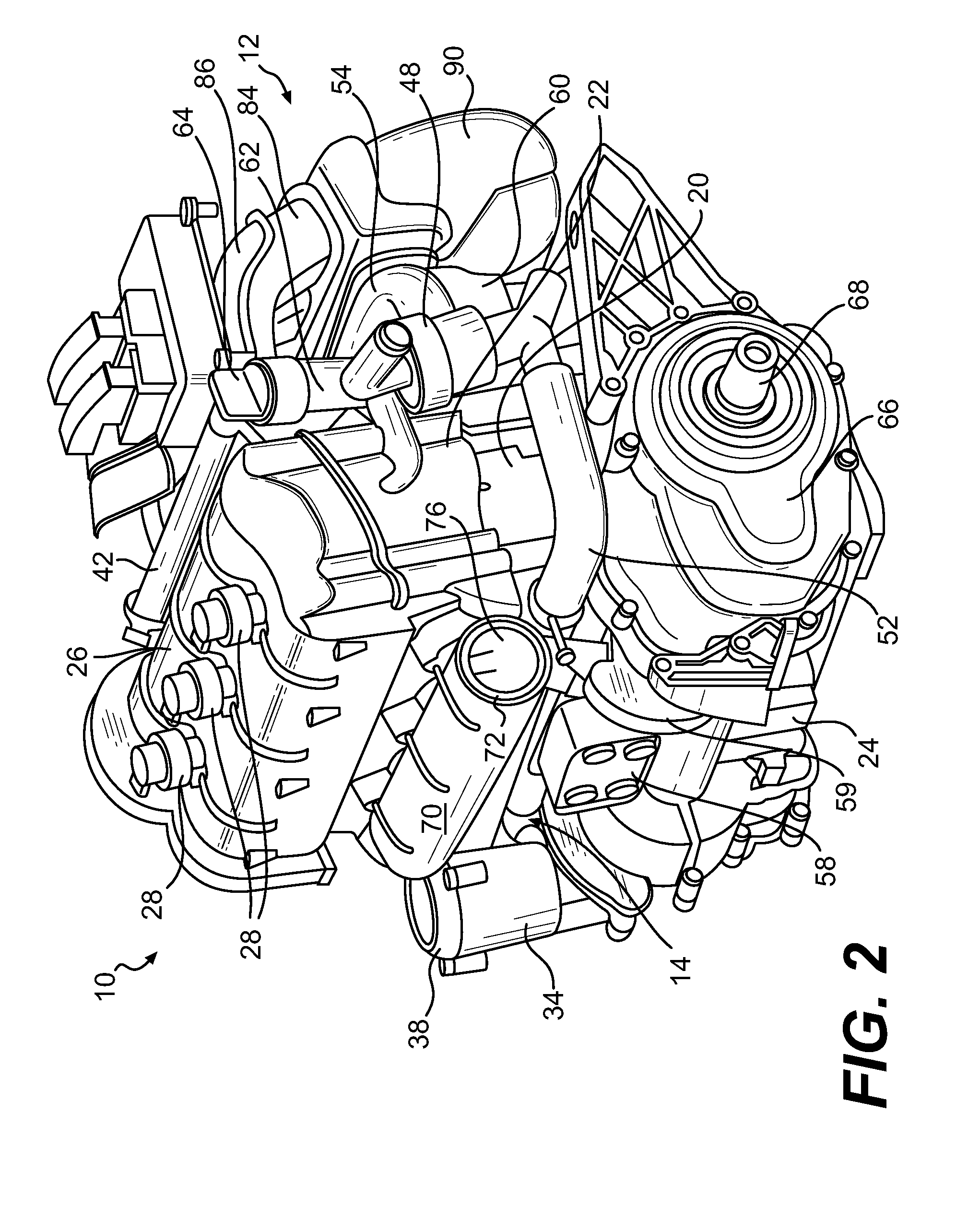
[0069]Turning now to the drawings and referring first to FIGS. 1 to 8, external features of the engine 10 will be described. As can be seen by comparing the embodiment of the engine 10 illustrated in FIGS. 1 to 4 to the embodiment of the engine 10 illustrated in FIGS. 5 to 8, i...


PUM


Abstract

An internal combustion engine (10) dry sump lubrication system including multiple oil paths through the engine, the engine being constructed and arranged such that when the engine is mounted on a vehicle and the vehicle is level and upright and the engine is not in operation, oil in each of the multiple oil paths collects at oil collection portions (3,26,514,516) within the engine, each oil collection portion being at a low portion with respect to gravity in one of the oil paths; a plurality of oil drainage openings (510,512,508) fluidly connected to the oil collection portions; and a single drain plug (500) simultaneously removeably sealing each of the oil drainage openings, whereby substantially all of the oil in the system is drained from the system when the single drain plug is removed.

Description

CROSS-REFERENCE TO RELATED APPLICATIONS[0001]The present application claims the benefit of prior to U.S. Provisional Patent Application No. 61 / 025,247 filed on Jan. 31, 2008 entitled “Lubrication System for a Dry Sump Internal Combustion Engine”. The present application is also related to U.S. Provisional Patent Application No. 60 / 948,283 filed on Jul. 6, 2007 and U.S. patent application Ser. Nos. 11 / 960,543, 11 / 960,557, and 11 / 960,566, all filed on Dec. 19, 2007. The entirety of each one of the aforementioned provisional applications is incorporated herein by reference.FIELD OF THE INVENTION[0002]The present invention relates to lubrication systems for dry sump internal combustion engine.BACKGROUND OF THE INVENTION[0003]A dry sump is a lubricating oil management strategy for four-stroke and large two-stroke piston internal combustion engines that uses an external secondary reservoir for oil, as compared to a conventional wet sump system.[0004]Four stroke engines, for example, are l...

Claims


Application Information

Patent Timeline
Patent Type & Authority Patents(United States)
IPC IPC(8): F01M1/02
CPCF01M1/12F01M11/02F01M11/0408F01M2001/126F01M2011/0416
Inventor KUSEL, RUDOLF
Owner BRP ROTAX
Why Eureka
Try Eureka