
Positive-pressure flying aircraft

a technology of flying aircraft and positive pressure, which is applied in the direction of hybrid airships, fuselages, transportation and packaging, etc., can solve the problems of difficult ground running with a very large angle of attack, and achieve the effect of stable fligh

Active Publication Date: 2013-06-18
BELLSION
View PDF14 Cites 4 Cited by
  • Summary
  • Abstract
  • Description
  • Claims
  • Application Information

AI Technical Summary

Benefits of technology

[0007]It is an object of the invention to provide a positive-pressure flying aircraft that does not comprise a cantilever wing having a free end, the aircraft flying by relative air stream, assuring stable flight in landing / takeoff or at low speed.

Problems solved by technology

In low-speed flight and landing, the angle of attack of the whole aircraft has to be made very large and it is very difficult to run on the ground with the very large angle of attack.

Method used


Image

  • Positive-pressure flying aircraft
  • Positive-pressure flying aircraft
  • Positive-pressure flying aircraft

Examples


Embodiment Construction

[0013]An embodiment of the present invention will be described with respect to the drawings.

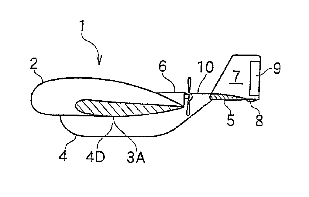
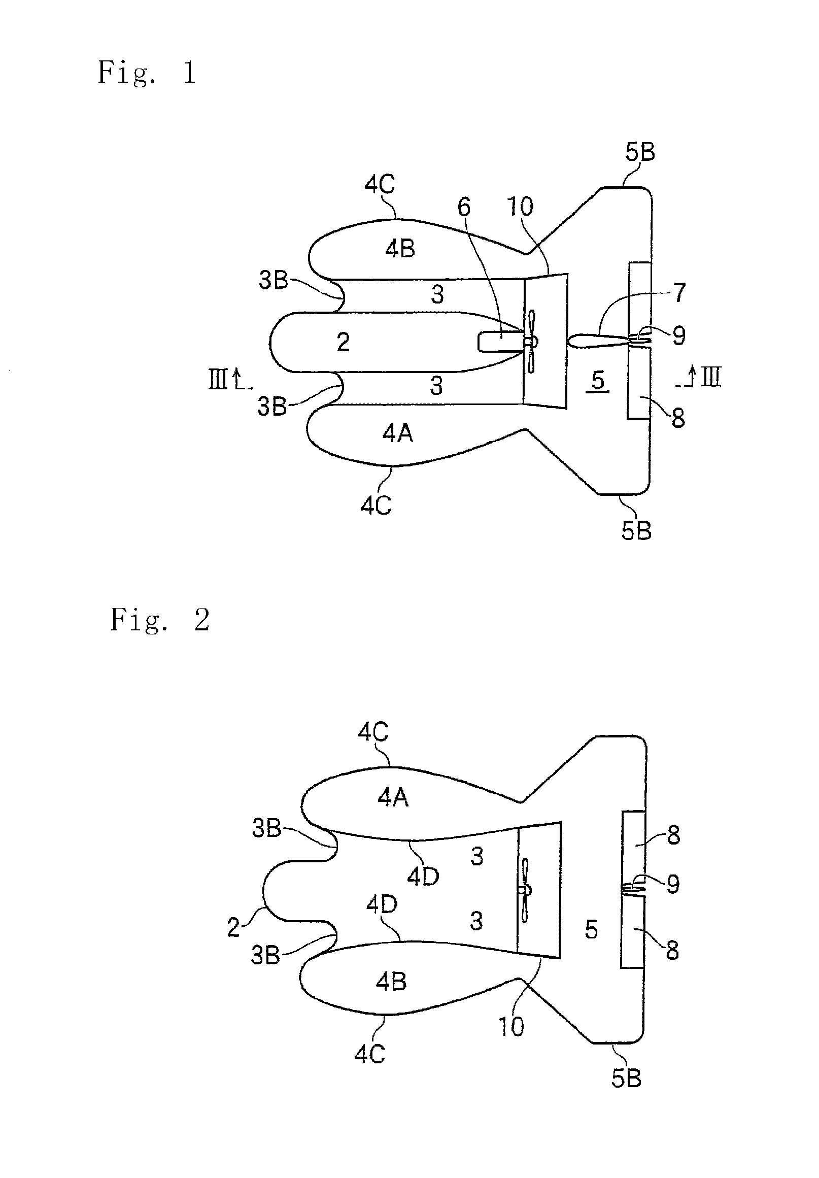
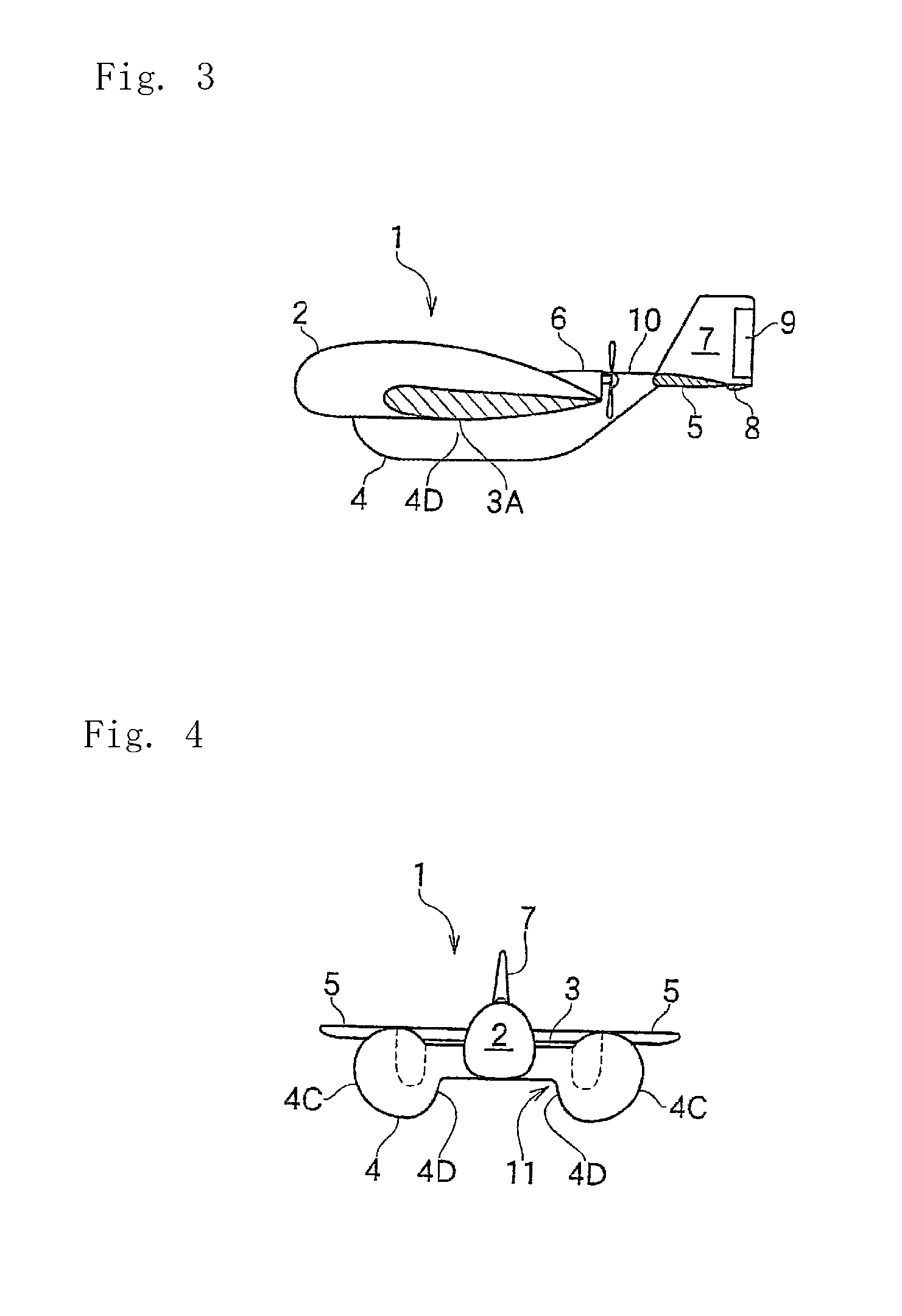
[0014]In FIGS. 1 and 2, differently from a conventional aircraft, a positive-pressure flying aircraft in this embodiment is characterized in that the aircraft that is different from a conventional aircraft has not a long wing extending transversely.

[0015]The aircraft comprises a main body 2 in the middle; a wing 3 projecting transversely from the lower part of the main body 2; a right body 4A and a left body 4B fixed to each side of the wing 3; a horizontal stabilizer 5 at the rear ends of the right and left bodies 4A, 4B; and a propeller 6 at the upper and rear end of the main body 2. On the horizontal stabilizer 5, a vertical fin 7 and an elevator 8 are provided, while a rudder 9 is provided on the vertical fin 7.

[0016]Between the front edge of the horizontal stabilizer 5 and the rear edge of the wing 3, there is formed a gap 10 in which the propeller 6 is disposed.

[0017]The vertical fin 7 ...


PUM


Abstract

A positive-pressure floating type airplane comprising an airfoil portion, left-right fuselages, a central fuselage, an elevator and a rudder disposed at the back of the airfoil portion, a thruster disposed at the back of the central fuselage, and a horizontal stabilizer disposed at the rear ends of the left-right fuselages. The individual front ends of the airfoil portion, the left-right fuselages and the central fuselage are formed into arcuate shapes in longitudinal sections. On the lower side of the airfoil portion, a recessed air capture is formed from the front end to the rear end. As a result, the positive-pressure floating type airplane is floated by the reaction from the air at the time when the air to pass the air capture through the airfoil portion is pushed by the thrust of the thruster, and is propelled forward by the component of that thrust.

Description

CROSS REFERENCE TO RELATED APPLICATIONS[0001]The present application is a 35 U.S.C. §371 National Phase conversion of PCT / JP2008 / 064471, filed Aug. 12, 2008, which claims benefit of Japanese Application No. 2007-239298, filed Sep. 14, 2007, the disclosure of which is incorporated herein by reference. The PCT International Application was published in the Japanese language.TECHNICAL FIELD[0002]The present invention relates to a positive-pressure flying aircraft, and particularly to a positive-pressure flying aircraft that does not comprise a cantilever wing, the aircraft flying by relevant stream or positive pressure flowing along the lower surface of the aircraft.BACKGROUND OF THE INVENTION[0003]An aircraft provides lift by negative pressure along the upper surface of a wing because of difference in velocity of air stream flowing on the upper and lower surfaces.[0004]JP2004-106784A discloses a kite-type aircraft that flies by air stream or positive pressure.[0005]In the kite-type ai...

Claims


Application Information

Patent Timeline
Patent Type & Authority Patents(United States)
IPC IPC(8): B64C39/00
CPCB60V1/08B64C39/04B64B2201/00
Inventor SUZUKI, MASAHIKO
Owner BELLSION
Learn More