Light source module and vehicle lamp

a technology of light source module and vehicle lamp, which is applied in the direction of fixed installation, lighting and heating apparatus, lighting support devices, etc., can solve the problems of large loss of power consumption and blurred light distribution pattern, and achieve the effect of reducing power consumption, high accuracy, and reducing power consumption

Inactive Publication Date: 2013-06-18
KOITO MFG CO LTD
View PDF8 Cites 3 Cited by
  • Summary
  • Abstract
  • Description
  • Claims
  • Application Information

AI Technical Summary

Benefits of technology

[0007]One or more embodiments of the present provides a light source module that can reduce loss of power consumption while forming an appropriate light distribution pattern, and a vehicle lamp using the light source module.
[0009]According to this aspect, the light emitting area of each of the semiconductor light emitting elements, which are positioned inside both ends of the light source module, is smaller than that of each of the semiconductor light emitting elements that are positioned at both ends of the light source module. Accordingly, current density becomes high, so that light-emitting luminance becomes high. If a vehicle lamp unit is formed using the light source module such that the optical center of the optical system is positioned on the middle line of the array of the semiconductor light emitting elements, the luminance of the semiconductor light emitting elements, which are positioned inside both ends of the light source module, is increased. Accordingly, the amount of light passing through the optical center of the optical system is increased, and thus it becomes possible to form a bright light distribution pattern with high accuracy. Further, since the luminance of a portion, which has relatively high use efficiency of light used to form a light distribution pattern, is increased, it may be possible to reduce loss of power consumption.
[0010]The light emitting areas of the semiconductor light emitting elements may be formed to be decreased toward the inside of the light source module from both ends of the light source module. In this case, the luminance of the semiconductor light emitting elements is increased from both ends of the array of the semiconductor light emitting elements toward the middle thereof. Since the proportion of light, which is effectively used to form a light distribution pattern, is increased toward the middle of the array of the semiconductor light emitting elements, the luminance of the semiconductor light emitting elements is increased from both ends of the array of the semiconductor light emitting elements toward the middle thereof. Accordingly, it may be possible to form a bright light distribution pattern with higher accuracy. Moreover, it may be possible to further reduce loss of power consumption.
[0011]The number of the semiconductor light emitting elements may be an odd number of 3 or more. The light emitting area of the semiconductor light emitting element, which is positioned in the middle, may be formed to be smaller than the light emitting area of each of the semiconductor light emitting elements that are positioned at both ends. In this case, it may be possible to form a more preferable light distribution pattern by positioning the optical center of the optical system on a line that passes through the semiconductor light emitting element positioned in the middle of the array. Further, it may be possible to suppress the generation of streaky lines that have low luminosity and are formed near the middle of the light distribution pattern.
[0013]According to this aspect, it may be possible to form a vehicle lamp that can reduce power consumption while forming a bright light distribution pattern with high accuracy.
[0014]According to one or more embodiments of the invention, it may be possible to provide a light source module that can reduce power consumption while forming an appropriate light distribution pattern, and a vehicle lamp using the light source module.

Problems solved by technology

However, in employing the light source module disclosed in Patent Document 1, there is a concern that a light distribution pattern becomes blurred by the light emitted from the semiconductor light emitting elements that are positioned at both ends, separated from the middle of the array of the semiconductor light emitting elements.
However, since the light emitted from the semiconductor light emitting elements, which are positioned at both ends of the array, is not efficiently used to form a light distribution pattern, loss of power consumption is large.

Method used


Image

  • Light source module and vehicle lamp
  • Light source module and vehicle lamp
  • Light source module and vehicle lamp

Examples


Embodiment Construction

[0022]Embodiments of the invention will be described in detail below with reference to drawings. In embodiments of the invention, numerous specific details are set forth in order to provide a more thorough understanding of the invention. However, it will be apparent to one of ordinary skill in the art that the invention may be practiced without these specific details. In other instances, well-known features have not been described in detail to avoid obscuring the invention.

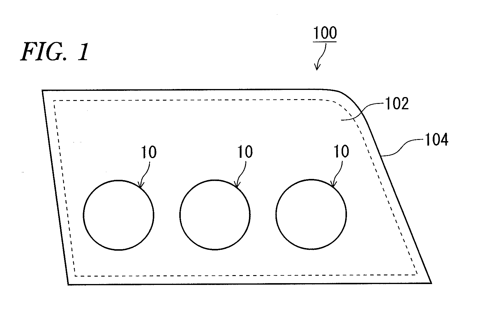
[0023]FIG. 1 is a front view of a vehicle lamp 100 according to an embodiment of the invention. For example, the vehicle lamp 100 is a low beam irradiation vehicle headlamp that emits light in a certain irradiation direction to the area in front of the vehicle. The vehicle lamp 100 includes three vehicle lamp units 10 that are arranged in a horizontal line and housed in a lamp chamber. The lamp chamber is formed by a lamp body 104 and a transparent cover 102 which allows most of light to penetrate therethrough wit...


PUM


Abstract

A light source module for a vehicle lamp, including an optical system that guides light emitted from the light source module in a certain irradiation direction and has an optical center, the light source module has a plurality of semiconductor light emitting elements disposed in a straight line and electrically connected to each other in series. One of the semiconductor light emitting elements that is positioned closest to the optical center of the optical system has a light emitting area that is smallest of the plurality of the semiconductor light emitting elements.

Description

TECHNICAL FIELD[0001]The present invention relates to a light source module using semiconductor light emitting elements and a vehicle lamp using the light source module.BACKGROUND ART[0002]A vehicle headlamp using semiconductor light emitting elements such as LEDs (Light Emitting Diodes) has been known. The vehicle headlamp needs to form a certain light distribution pattern from the viewpoint of safety or the like.[0003]Further, a sufficient amount of light has to be secured in the vehicle headlamp. For this reason, it is studied that a plurality of semiconductor light emitting elements are used in the vehicle headlamp. For example, Patent Document 1 discloses a vehicle headlamp using a light source module including a plurality of semiconductor light emitting elements. The semiconductor light emitting elements are electrically connected in series, have substantially the same light emitting area, and are disposed in a straight line.[0004][Patent Document 1] JP-A-2005-294166SUMMARY OF...

Claims


Application Information

Patent Timeline
Patent Type & Authority Patents(United States)
IPC IPC(8): F21S8/10F21V21/00
CPCF21S48/1154F21S48/1159F21S48/1747F21V29/763F21V29/75F21S48/328F21V29/004F21Y2101/02F21V13/12F21S41/143F21S41/148F21S41/151F21S41/663F21S45/48F21V13/14F21Y2115/10
Inventor SASAKI, YASUTAKAISHIDA, HIROYUKI
Owner KOITO MFG CO LTD
Why Eureka
Try Eureka