
Autonomous balancing of series connected charge storage devices

a charge storage device and autonomous balancing technology, applied in the direction of transportation and packaging, ac network voltage adjustment, and arrangement of several simultaneous batteries, can solve the problems of limiting the charging to a single cell at a time, wasting heat energy being discharged by this method, and affecting the efficiency of the charging process, etc., to achieve the effect of low power, low cost and low cos

Inactive Publication Date: 2013-06-18
INT BATTERY
View PDF17 Cites 12 Cited by
  • Summary
  • Abstract
  • Description
  • Claims
  • Application Information

AI Technical Summary

Benefits of technology

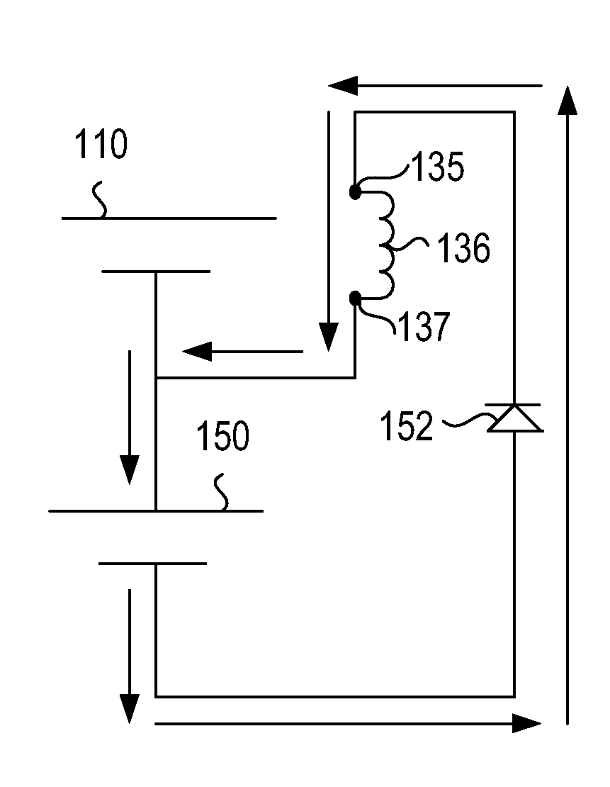
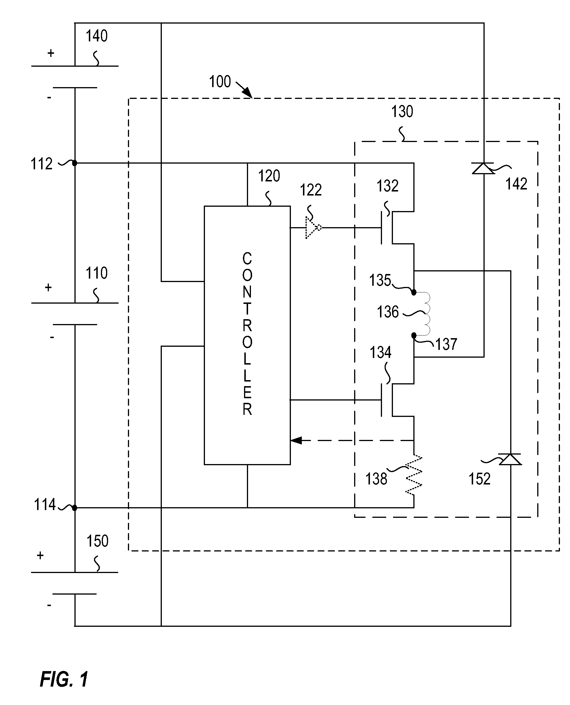
The patent describes a charge balancing circuit for a series connected charge storage unit. This circuit can operate without a central controller and can actively balance each storage unit at the same time, which makes the overall balancing process faster. The circuit is designed to use low voltage components and interconnects, which leads to higher efficiency and lower costs. This allows for the use of low-voltage components that have low on-resistance, which results in less waste heat and better performance.

Problems solved by technology

Mismatches between the cells may cause the cells to experience undervoltage or overvoltage conditions that are undesirable.
The mismatches may be caused by manufacturing tolerances in the initial production of the cells, age difference between cells, or differences in the state of charge.
Though simple and low cost, the energy being discharged by this method is wasted as heat.
The single current source may also limit the charging to a single cell at a time.
Such an arrangement may limit the balancing to sets of adjacent cells.
Another method may include complicated control and switching arrangements to transfer charge between cells.

Method used


Image

  • Autonomous balancing of series connected charge storage devices
  • Autonomous balancing of series connected charge storage devices
  • Autonomous balancing of series connected charge storage devices

Examples


Embodiment Construction

[0015]The ensuing detailed description provides preferred exemplary embodiments only, and is not intended to limit the scope, applicability, or configuration of the invention. Rather, the ensuing detailed description of the preferred exemplary embodiments will provide those skilled in the art with an enabling description for implementing the preferred exemplary embodiments of the invention. It being understood that various changes may be made in the function and arrangement of elements without departing from the spirit and scope of the invention, as set forth in the appended claims.

[0016]To aid in describing the invention, directional terms are used in the specification and claims to describe portions of the present invention (e.g., upper, lower, left, right, etc.). These directional definitions are merely intended to assist in describing and claiming the invention and are not intended to limit the invention in any way. In addition, reference numerals that are introduced in the spec...


PUM


Abstract

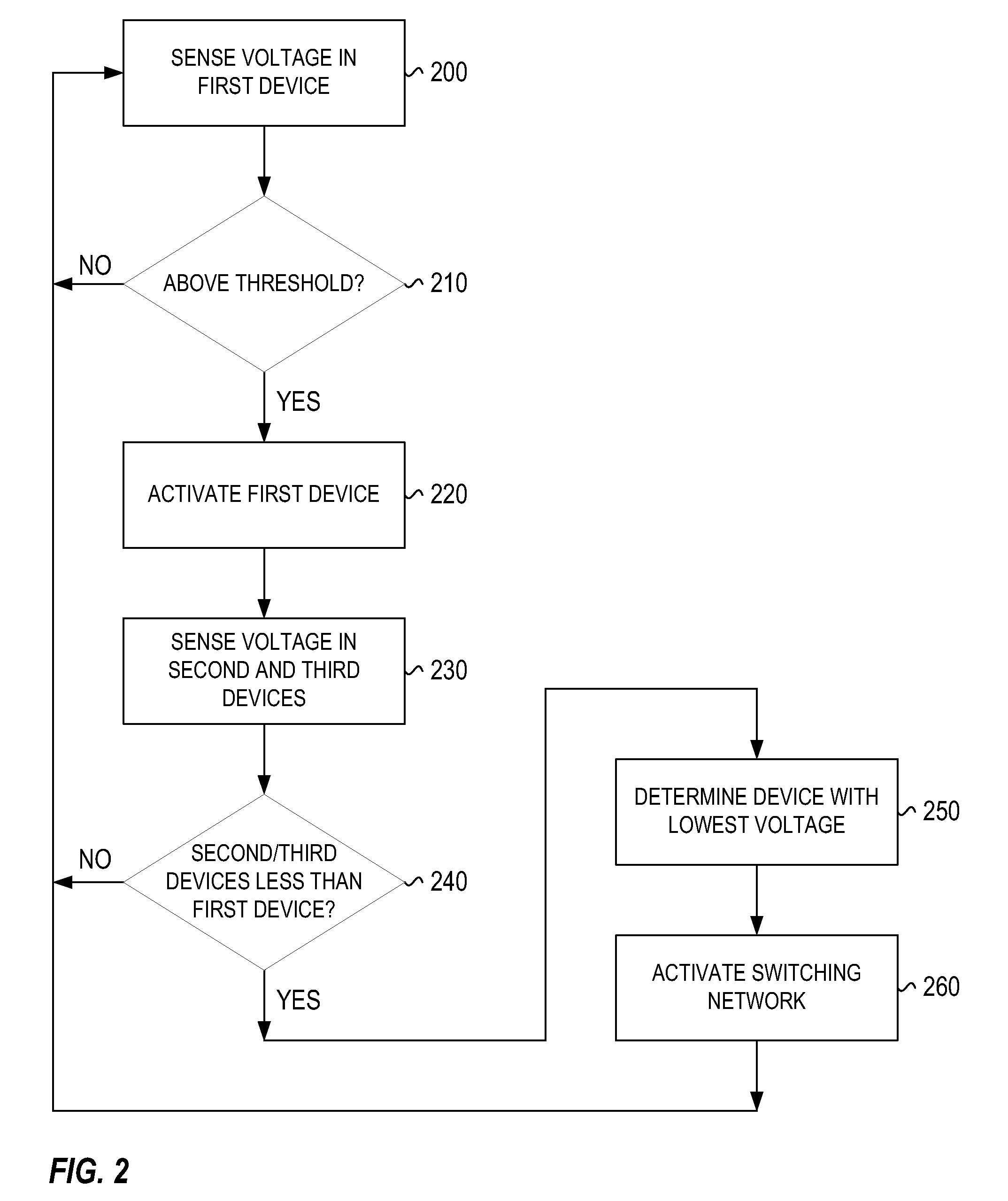
A charge balancing circuit implemented within a charge storage device (cell) in a series connected charge storage unit (battery) made up of a plurality of cells. The charge balancing circuit may utilize a controller to sense the voltage in the cell it is implemented therein and the cells adjacent thereto. If the voltage of the current cell exceeds a threshold voltage and is greater than at least one adjacent cell the current cell can transfer charge to the adjacent cell having the lowest voltage. The transfer of the charge is done with a switching network that extracts current from the current cell and then transfers the current to the adjacent cell having the lowest voltage. The switching network may utilize switches and a current storage device (inductor) to transfer the charge. The controller may activate different switches based on which adjacent cell has the lowest voltage.

Description

BACKGROUND[0001]When there is a need for energy storage at voltages greater than a single cell can provide, individual cells can be connected in a series arrangement to generate a higher voltage series connected battery. Mismatches between the cells may cause the cells to experience undervoltage or overvoltage conditions that are undesirable. Some cell chemistries may be particularly sensitive to the undervoltage or overvoltage conditions. The mismatches may be caused by manufacturing tolerances in the initial production of the cells, age difference between cells, or differences in the state of charge. Maintaining the cells in balance in order to avoid undervoltage or overvoltage conditions is a critical design goal that produces a reliable and safe battery having a long operating cycle life.[0002]Maintaining the cells in balance may require charging and discharging individual cells. One method for discharging is resistive loading of individual cells. Though simple and low cost, the...

Claims


Application Information

Patent Timeline
Patent Type & Authority Patents(United States)
IPC IPC(8): H02J7/00H02J3/00
CPCH02J7/0019
Inventor BUONO, ROBERT N.GOW, PHILIPE H.
Owner INT BATTERY
Learn More