Video calibration device

a video calibration and video technology, applied in the direction of optical radiation measurement, pulse technique, instruments, etc., can solve the problems of inability to use devices in front projection systems, inability to accurately perform front projector calibration, and easy leakage of light between the screen and the actual sensor, etc., to achieve accurate analysis of video images

Inactive Publication Date: 2013-06-18
CIESCO THOMAS E
View PDF3 Cites 2 Cited by
  • Summary
  • Abstract
  • Description
  • Claims
  • Application Information

AI Technical Summary

Benefits of technology

[0008]Bearing in mind the problems and deficiencies of the prior art, it is therefore an object of the present invention to provide a video calibration device which allows accurate analysis of a video image regardless of ambient light conditions.

Problems solved by technology

The difficulty lies in the situation where the analysis must be performed in different ambient light settings than that of during viewing of the display.
Pod style analyzers which lie flat against the screen may aid in this situation, but is usually limited to rear projection and self emitting displays such as LCD, CRT, LCOS, DLP, and Plasma.
Front projector calibration cannot be performed accurately since the pod itself will block the light from reaching the screen at the position where the light sample is generally taken.
Even when used on the self emitting displays, light can easily leak in between the screen and the actual sensor since most of the pods have the sensor set back a small distance from the screen by a series of suction cups.
These devices cannot be used in front projection systems and are questionable in their ability to screen all ambient light.
The problem of ambient light affecting desired readings in an optical sensor may pertain to color analyzers, spectrophotometers, tri-stimulus sensors as well as any type of optical sensor or light wave sensors.

Method used


Image

  • Video calibration device
  • Video calibration device
  • Video calibration device

Examples


Embodiment Construction

)

[0042]In describing the preferred embodiment of the present invention, reference will be made herein to FIGS. 1-15 of the drawings in which like numerals refer to like features of the invention.

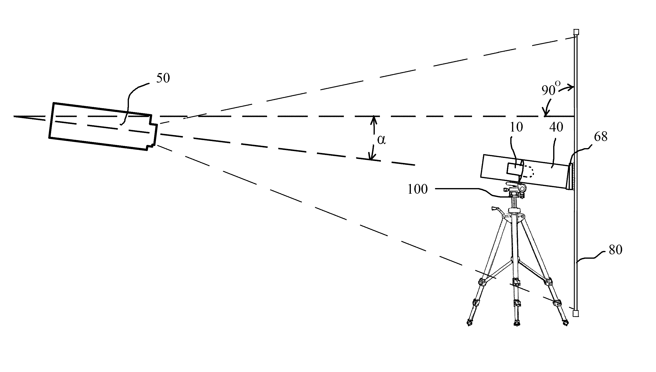
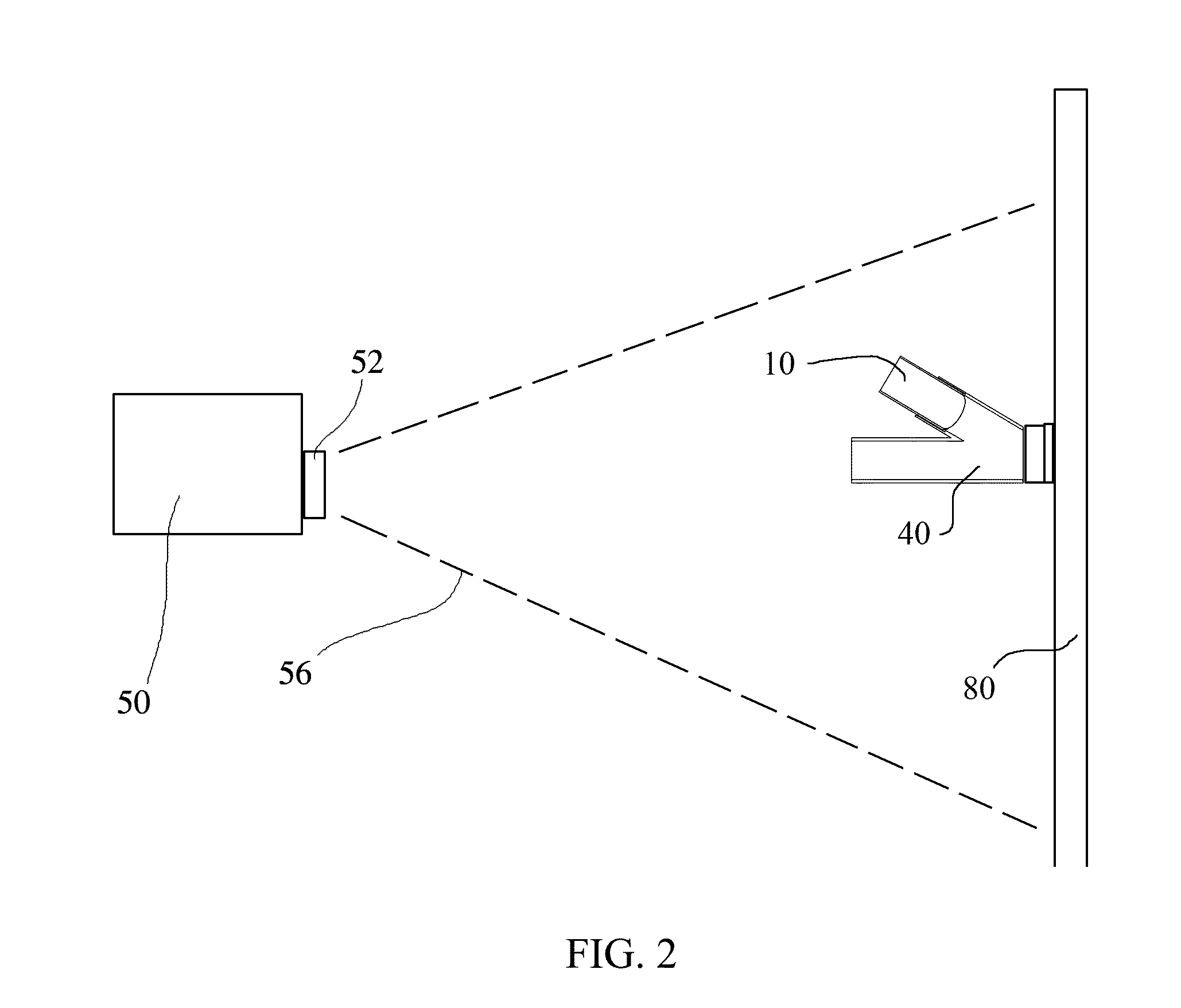
[0043]The device of the present invention is a video calibration device which includes a light block apparatus and preferably includes a calibration sensor. The calibration sensor may be a light wave analyzer, color analyzer, spectrophotometer, optical sensor, tri-stimulus sensor, video calibration sensor or any of a variety of devices used to measure qualities of light for the purpose of calibration or analysis.

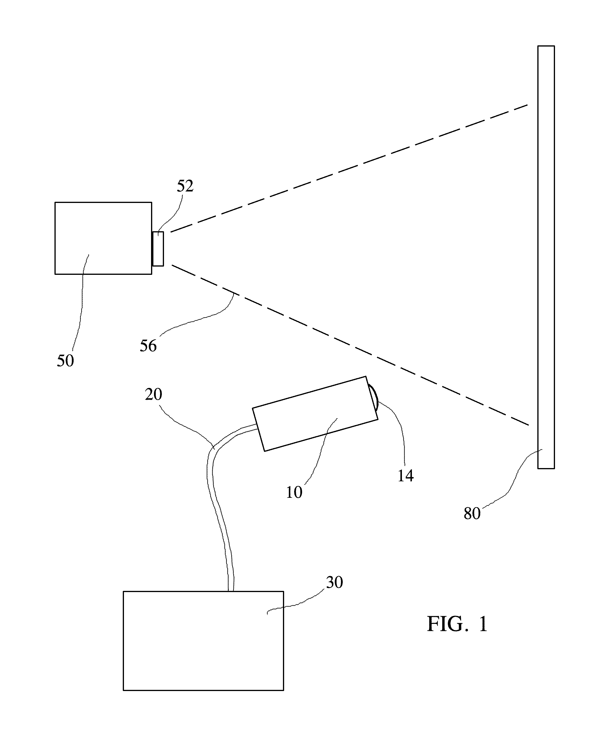
[0044]FIG. 1 shows a video calibration system which includes a light wave analyzer or optical sensing device 10 and a computer 30 with software for analysis of a signal sent by the sensor 10 through a connectivity source 20, the connectivity source preferably being a wire cable but alternatively implementing a signal using infrared waves or higher frequency signal waves. A projector ...


PUM


Abstract

A video calibration device comprising an elongated image tube having a length, a first opening at one end of the image tube and a second opening at the opposite end of the image tube. The device includes an elongated sensor tube having a length, a first opening at one end of the sensor tube and a second opening at the opposite end of the sensor tube. The first opening of the sensor tube is adapted to support a video calibration sensor. A video calibration sensor is disposed in the first opening of the sensor tube. The sensor tube is sealingly secured to the image tube at an angle whereby the second opening of the sensor tube and the second opening of the image tube are substantially juxtaposed.

Description

BACKGROUND OF THE INVENTION[0001]1. Field of the Invention[0002]The present invention relates to an apparatus for measuring light characteristics on a video screen and for the calibration of video output devices such as video monitors, video projectors and the like.[0003]2. Description of Related Art[0004]When calibrating displays such as flat screen televisions, video projector and screen systems and video monitors there are several color analyzers on the market which can accurately measure the light being emitted by the display. The analysis includes measuring light output of a display at different frequencies or different colors. Although each may measure the light emitted by the display accurately, light added to the display from other sources will be included in the analysis results. The difficulty lies in the situation where the analysis must be performed in different ambient light settings than that of during viewing of the display. An example of this would be where a calibra...

Claims


Application Information

Patent Timeline
Patent Type & Authority Patents(United States)
IPC IPC(8): H04N17/00H04N17/02
CPCH04N17/04G01J3/0262G01J1/0271G01J3/0291G01J1/0466G01J1/06G01J3/0289G01J3/50G01J1/0266G01J1/0214G01J1/0219G01J3/0213G01J1/0411G01J3/0264G01J3/0208G01J1/0418
Inventor CIESCO, THOMAS E.
Owner CIESCO THOMAS E
Why Eureka
Try Eureka