Ink tank

a technology of ink tanks and ink sheets, applied in the field of ink tanks, can solve the problems of excessively dense ink in the bottom excessively light ink in the uppermost portion of the ink tank, and print matters with dye inks to exhibit, so as to achieve stable ink led out or supplied, effective prevention of problems, and high agitation performan

Active Publication Date: 2013-06-25
CANON KK
View PDF12 Cites 23 Cited by
  • Summary
  • Abstract
  • Description
  • Claims
  • Application Information

AI Technical Summary

Benefits of technology

[0021]An object of the present invention is to provide an ink tank capable of: effectively preventing a problem that high-concentration ink containing a sedimentary pigment is led out; exerting higher agitating performance; and stabilizing the amount of ink led out or supplied.
[0023]In the present invention, the ink leading-out port, which is placed in the ink containing chamber and is used to supply the ink to a printing head, is located higher than the lowermost portion of the ink containing chamber. In addition, the ink leading-out port is formed in the inclined surface inclined to the gravitational direction. For this reason, even in a case where an ink tank containing ink including pigment components is left unused while mounted on the printing apparatus for a long period of time, the ink tank is capable of preventing high-concentration and high-viscosity ink containing a sedimentary pigment from being supplied to the ink leading-out port and further to the ink supply port.
[0024]Thereby, most of the sedimentary pigment are settled down in the ink containing chamber. For this reason, in the configuration in which agitating members are provided in the ink containing chamber, the ink can be sufficiently agitated by causing a carriage to reciprocate for a short time before a printing operation. Accordingly, the printing operation can be started immediately after the printing apparatus is activated. In addition, the ink tank is capable of homogenizing the concentration of the pigment, and thus enables the printing apparatus to print a high-quality image. Moreover, the ink tank is capable of reducing the amount of ink to be discharged when a printing operation is started after the ink tank is left unused for a long period of time, and accordingly reducing the running costs.
[0025]Additionally, even when the ink tank is configured to lead out ink, without taking atmosphere thereinto, but with a volume change of the ink containing chamber caused by displacement or deformation of a flexible member, the formation of the ink leading-out port in the inclined surface reduces the possibility that the ink leading-out port is closed by the flexible member. Accordingly, the ink tank allows the ink in the ink containing chamber to be ejected without waste, and thus offers a higher efficiency of ink use.

Problems solved by technology

However, it is difficult to cause printed matters with dye inks to exhibit as high performances as those required for application such as an outdoor printed display for which light resistance and weather resistance are considered important.
Nevertheless, pigment particles in pigment ink inevitably are settled down in an ink tank because the pigment is not of a solution type, but of a dispersion type.
As a result, ink in the bottom portion of the ink tank forms an excessively-dense color layer due to a higher concentration of the pigment particles, whereas ink in the uppermost portion of the ink tank forms an excessively-light color layer due to a lower concentration of the pigment particles.
When ink led out of such an ink tank is supplied to a printing head, the ink in the layer with a higher concentration of pigment particles is supplied first, thereby printing an image with an excessively-dense color.
However, the ink tanks respectively described in Japanese Patents Laid-open Nos. 2004-216761 and 2005-066520 have the following problems.
However, since multiple ink tanks are mounted on the single carriage in the movement direction of the carriage in many cases, the ink tank inevitably has to be formed with a relatively small width.
In addition, in a case where the acceleration of the carriage is set larger to elastically deform the agitating body to a larger extent, a larger and more expensive driving source (a motor or the like) may be needed for the carriage, and the printing apparatus may cause larger vibrations.
In the ink tank disclosed in Japanese Patent Laid-open No. 2005-066520 including the agitating body freely movable on the bottom surface of the ink tank, the agitating body has a problem of having a poor capability of agitating an upper portion of the ink in the ink tank because the agitating body is away from the upper portion of the ink.
For this reason, it is difficult to set the agitating body to be largely displaceable in its displacement direction that is in parallel with the movement direction of the carriage.
As a result, the amount of displacement of the agitating body is so small that strong flow of the ink cannot be caused.
This limits the agitating body's agitating efficiency of the ink, and requires too much time to fully agitate the ink in the ink tank.
Even if the ink tank is left unused for several days, the ink in the ink tank may have a concentration distribution having adverse affects on printed images.
In this case, the ink needs to be agitated every several days, and the printing apparatus can start no printing operation each time the ink is agitated.
For this reason, if the ink leading-out port in the ink containing chamber is formed in a horizontal surface when the ink tank is placed at a posture for use, most of the sedimentary pigment settled around the ink leading-out port may move into the ink leading-out port and further to the inside of the ink supply port, so that a desired effect cannot be obtained.
This configuration, however, has the following problem in the case where the ink tank includes a flexible member for changing the volume of the ink containing chamber, and is configured to change the volume of the ink containing chamber in order to alleviate the increase in a negative pressure with the leading-out (consuming) of the ink while taking no atmosphere thereinto.
However, depending on the height of a member forming the ink leading-out port, the agitating body has to be configured to avoid an interference with the member, so that the agitate body cannot be placed in a position where it can agitate effectively, or may be formed in a complicated shape.
Consequently, the agitating performance of the agitating body may decrease.

Method used


Image

  • Ink tank
  • Ink tank
  • Ink tank

Examples


second embodiment

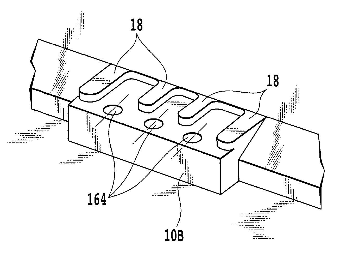
[0091]FIG. 11A is a schematic perspective view showing an internal configuration of an ink tank according to a second embodiment of the present invention. FIG. 11B is a partially enlarged view showing the internal configuration thereof. Component parts which are the same as those of the first embodiment will be denoted by the same reference numerals, and descriptions thereof will be omitted.

[0092]The ink tank according to this embodiment includes three ink leading-out ports 164 formed in a flat surface. This forming surface is not a horizontal surface, but a surface which is inclined to the gravitational direction when the ink tank is attached to the printing apparatus. In a case where the tank case 10 is a resin-molded component, the inclination angle of this forming surface may be an angle formed corresponding to a generally-used draft which is needed when a die is formed. In addition, convex-shaped bumps 18 extend from the inner wall 10A of the ink containing chamber along both o...


PUM


Abstract

An ink tank containing ink including a pigment component effectively prevents a problem that an ink having a higher concentration and including a sedimentary pigment is led out, even in a case where the ink tank is left unused on a printing apparatus for a long time. To this end, an ink leading-out port placed in an ink containing chamber, and used to supply the ink to a printing head is located higher than a lowermost portion of the ink containing chamber, and is also formed in an inclined surface inclined to a gravitational direction. Thereby, the sedimentary pigment slides the inclined surface, and thus is settled down in a position away from the ink leading-out port.

Description

BACKGROUND OF THE INVENTION[0001]1. Field of the Invention[0002]The present invention relates to an ink tank used for an inkjet printing apparatus and the like.[0003]2. Description of the Related Art[0004]Examples of a printing apparatus using ink contained in an ink tank include an inkjet printing apparatus using an inkjet printing head capable of ejecting the ink. In addition, one of such inkjet printing apparatuses is a serial scan type apparatus having an inkjet printing head and an ink tank mounted on a carriage and configured to print an image on a printing medium while moving the carriage.[0005]This serial scan type inkjet printing apparatus includes a carriage capable of mounting an inkjet printing head and an ink tank for supplying ink to the printing head. In printing, the apparatus causes the printing head to eject ink droplets through fine ejection openings provided in the printing head while moving the carriage relative to the printing medium. Thus, the ink droplets lan...

Claims


Application Information

Patent Timeline
Patent Type & Authority Patents(United States)
IPC IPC(8): B41J2/175
CPCB41J2/17513
Inventor OHASHI, TETSUYAKOTAKI, YASUOINOUE, RYOJIKUBO, KOICHIOGASAWARA, MASASHI
Owner CANON KK
Why Eureka
Try Eureka