Plug connector, receptacle connector and electrical connector assembly

a technology of receptacle connectors and plug connectors, which is applied in the direction of coupling contact members, coupling device connections, electric discharge lamps, etc., can solve problems such as connector suffering, poor electrical transmission, and inability to transmit signals or even signals

Inactive Publication Date: 2013-06-25
CHENG UEI PRECISION IND CO LTD
View PDF12 Cites 16 Cited by
  • Summary
  • Abstract
  • Description
  • Claims
  • Application Information

AI Technical Summary

Benefits of technology

[0006]For overcoming above defects, an object of the present invention is to provide a plug connector, a receptacle connector and an electrical connector assembly, which can form a stable connection and provide a stable signal transmission and are not easy to be effected by external shocks.
[0009]To achieve the above object, in accordance with the present invention, an electrical connector assembly is also provided, comprising a plug connector and a receptacle connector. The plug connector comprises a plug housing and a plurality of plug terminals located in the plug housing. Each plug terminal includes a first, second and third contact portions. The receptacle connector comprises a receptacle housing and a plurality of receptacle terminals mounted in the receptacle housing. Each receptacle terminal includes a first, second and third side portions. When the plug connector and the receptacle connector are combined together, the first, second and third contact portions respectively contact with the first, second and third side portions so that realizing a three-position contact between the plug and receptacle terminals for providing a stable signal transmission.
[0010]Based on the above description, the first, second and third contact portions of each plug terminal of the plug connector of the present invention respectively contact with the first, second and third side portions of each receptacle terminal of the receptacle connector of the present invention, so that the plug and receptacle terminals can realize a three-position contact for providing a stable signal transmission, assuring a stable combination and being not easy to be effected by external shocks.

Problems solved by technology

But the configuration of the traditional terminal only can contact with the complementary terminal on single position thereof, so that it is apt to slip from the complementary terminal and result in unstable signal transmission or even signal interruption and so on and makes the connector suffer from the factors of the external shocks and the like.
But, the hard interference fit cannot provide a stable contact and is easily loosened and result in the bad electrical transmission because of the connector being pulled by the external shocks.

Method used


Image

  • Plug connector, receptacle connector and electrical connector assembly
  • Plug connector, receptacle connector and electrical connector assembly
  • Plug connector, receptacle connector and electrical connector assembly

Examples


Embodiment Construction

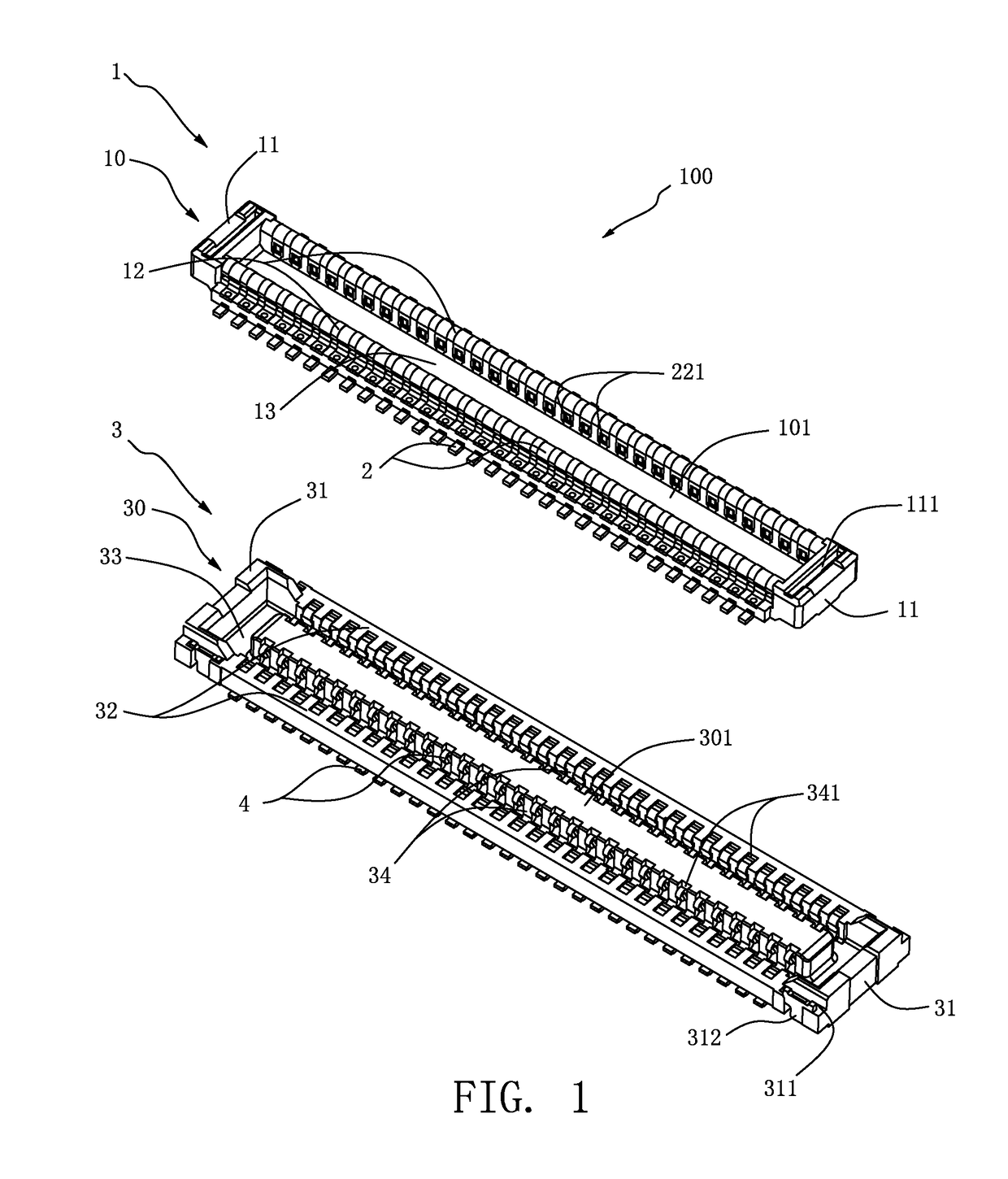
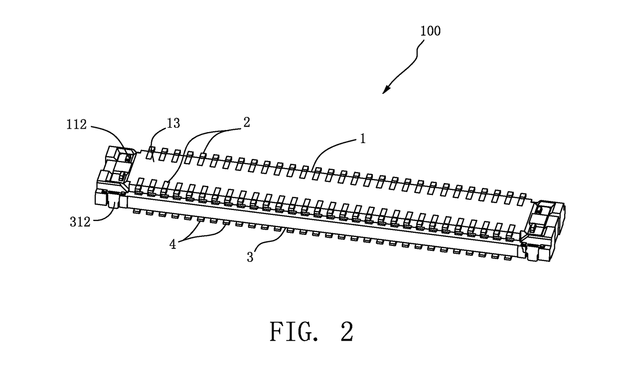
[0016]Please refer to FIGS. 1 to 4, which are one preferred embodiment of an electrical connector assembly 100 of the present invention, the electrical connector assembly 100 of the present invention comprises a plug connector 1 and a receptacle connector 3 mated with each other.

[0017]Please again refer to FIGS. 1 and 3, the plug connector 1 comprises a plug housing 10 being rectangular strip-shaped and being made of insulating material. The plug housing 10 has two opposite end walls 11 extending along a short axis thereof, two opposite sidewalls 12 extending along a long axis thereof, and a bottom plate 13 connecting bottoms of the two end walls 11 and the two sidewalls 12. Each of the two end walls 11 disposes a positioning groove 111 passing through a top and bottom surfaces thereof. A flux member 112 (shown in FIG. 2) is mounted in the positioning groove 111 for strengthening the connection of the plug housing 10 and one circuit board (not shown in all FIGS.). The plug connector...


PUM


Abstract

A plug connector, a receptacle connector and an electrical connector assembly are provided. The plug connector includes a plug housing and a plurality of plug terminals located in the plug housing. Each plug terminal includes a first, second and third contact portions. The receptacle connector includes a receptacle housing and a plurality of receptacle terminals mounted in the receptacle housing. Each receptacle terminal includes a first, second and third side portions. When the plug connector and the receptacle connector are combined together to form the electrical connector assembly, the first, second and third contact portions respectively contact with the first, second and third side portions so that realizing a three-position contact between the plug and receptacle terminals for providing a stable signal transmission.

Description

BACKGROUND OF THE INVENTION[0001]1. Field of the Invention[0002]The present invention relates to a plug connector, a receptacle connector and an electrical connector assembly, and more particularly to a plug connector and a receptacle connector being mated together and to an electrical connector assembly having improved components, being capable of providing a stable hold and forming an electrical connection between two circuit boards.[0003]2. Description of the Prior Art[0004]At present, a connector mainly includes a housing and a plurality of terminals. The connector is mounted on a circuit board for being mated with a complementary connector. By the terminals of the two connectors contacting with each other, the two connectors form an electrical transmission therebetween. Therefore, the configuration of the terminal is one of the main factors of whether the terminal can provide a stable contact. In view of this, the traditional connector ordinarily disposes a plurality of termina...

Claims


Application Information

Patent Timeline
Patent Type & Authority Patents(United States)
IPC IPC(8): H01R13/00
CPCH01R12/716H01R24/60H01R12/73H01R13/20
Inventor HUANG, SHENG-YUAN
Owner CHENG UEI PRECISION IND CO LTD
Why Eureka
Try Eureka