
Method for determining orientation of electromagnetic receivers

a technology of electromagnetic receivers and orientation methods, applied in the field of geophysical prospecting, can solve the problems of compass measurements being subject to stray magnetic fields, all methods have limitations, and the orientation of the electric and magnetic antennae of the receiver is not typically reliable, so as to reduce the degree of mismatch

Inactive Publication Date: 2013-06-25
EXXONMOBIL UPSTREAM RES CO
View PDF9 Cites 1 Cited by
  • Summary
  • Abstract
  • Description
  • Claims
  • Application Information

AI Technical Summary

Benefits of technology

The technical effect of this patent text is to adjust the assumed angular orientation to reduce the degree of mismatch.

Problems solved by technology

One approach is to include a measurement system on the receivers, but these do not typically provide reliable information about the orientation of the receiver's electric and magnetic antennae.
All of these methods have limitations.
Compass measurements are subject to stray magnetic fields in the receivers and local errors in the static field measurements, and are not accurate enough for practical applications in subsurface hydrocarbon detections.
Polarization analysis alone is therefore unsuitable to predict these more sensitive components.
Orientations determined by this technique are furthermore subject to data limitation caused by receiver saturation (signals too large to be digitized), feathering of the CSEM source antenna, and breakdown of the one-dimensional earth approximation.
This method is even more strongly influenced by three-dimensional variation of the subsurface and is typically less accurate than polarization analysis.
It is, however, computationally intensive because multiple solutions of the forward modeling problem (i.e., solving Maxwell's equations by numerical methods) are required and sensitive to errors introduced by local minima in the objective function from both the variation of receiver orientations and the subsurface resistivities.

Method used


Image

  • Method for determining orientation of electromagnetic receivers
  • Method for determining orientation of electromagnetic receivers
  • Method for determining orientation of electromagnetic receivers

Examples


examples

[0078]The result of an example where the first embodiment of the present inventive method was used is shown in FIG. 6B. Crossline components of a broadside electric field are shown. The solid curves 61 are data at a frequency of 0.125 Hz from a tow line located 2.5 km from the receiver. The dashed curves 62 represent data at 0.125 Hz from a tow line 4.7 km from the receiver. The dotted curves 63 represent data at 1.25 Hz and tow line 2.5 km from the receiver. All curves in FIG. 6B reflect iteration to determine the best receiver orientation. FIG. 6A shows for comparison the same data resolved into the crossline direction using the orientation determined by polarization analysis. Thus, FIG. 6A represents a result from the present invention after an intelligent first guess at receiver orientation, whereas FIG. 6B shows the improvement after cycles of adjusting / updating of the orientation to better match the data. The improvement is demonstrated by positive offset ranges' being more sy...


PUM


Abstract

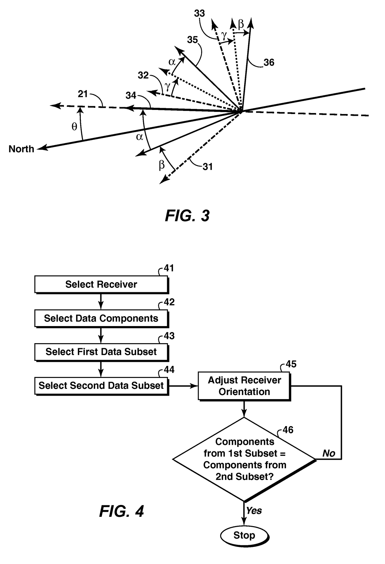
Method for determining receiver orientation angles in a controlled source electromagnetic survey, by analyzing the survey data. For a given survey receiver, two data subsets are selected. (43, 44). The two subsets may be from two offset ranges that are geometrically symmetrical relative to the receiver location. Alternatively, the second subset may be a computer simulation of actual survey data. In either instance, an orientation is assumed for the receiver (45), and that orientation is used to compare component data from the two subsets that can be expected to match if the assumed orientation angle(s) is (are) correct (46). The mismatch is ascertained, and the assumed orientation is adjusted (45) and the process is repeated.

Description

CROSS REFERENCE TO RELATED APPLICATIONS[0001]This application is the National Stage of International Application No. PCT / US2009 / 062211, that published as WO 2010 / 05373, filed 27 Oct. 2009, which claims the benefit of U.S. Provisional Application No. 61 / 111,168, filed 4 Nov. 2008, each of which is incorporated herein by reference, in its entirety, for all purposes.FIELD OF THE INVENTION[0002]This invention relates generally to the field of geophysical prospecting and more particularly to the field of electromagnetic surveying. Specifically, the invention is a method of determining the orientation of receivers used in marine controlled-source electromagnetic data acquisition by matching one subset of data to another.BACKGROUND OF THE INVENTION[0003]Controlled-source electromagnetic (“CSEM”) surveys are an important geophysical tool for evaluating the presence of hydrocarbon-bearing strata within the earth. CSEM surveys typically record the electromagnetic signal induced in the earth b...

Claims


Application Information

Patent Timeline
Patent Type & Authority Patents(United States)
IPC IPC(8): G01B7/30
CPCG01V3/083G01V3/12
Inventor PAVLOV, DMITRIY A.JING, CHARLIEWILLEN, DENNIS E.
Owner EXXONMOBIL UPSTREAM RES CO
Learn More