Vortex turbine cleaner

a technology of vortex turbines and cleaners, which is applied in the direction of public buildings, gymnasiums, buildings types, etc., can solve the problems of high wear and tear, and achieve the effect of high resistance tracks

Active Publication Date: 2013-07-02
STOLTZ HERMAN
View PDF8 Cites 25 Cited by
  • Summary
  • Abstract
  • Description
  • Claims
  • Application Information

AI Technical Summary

Benefits of technology

[0009]Blade drag is minimized as the water column rotates irrespective of whether a turbine is positioned in the rotating water column or not. The major benefit of the positioning of the turbine away from the direct path between inlet and outlet is the creation of an open channel insofar as water-flow or debris consumption is concerned.
[0010]This feature also creates the opportunity for inlet and outlet paths to be located in very close proximity to each other as no allowance has to be made for the placement of a turbine in-between the channels. Due to the efficiency of the vortex design, the turbine blades do not have to be cupped or curved like existing designs to achieve sufficient power for the intended purpose of the drive unit. Another benefit is that the rotating water column allows large debris to be rotated in a similar fashion within the chamber thereby positioning it to conform to the outlet channel. The design incorporates a very simple reversing mechanism by merely diverting the intake of flow to rotate the vortex in the opposite direction. Due to the blades not being cupped or curved to minimize drag, no power loss occurs. The benefit of this is that the drive gears remain in their respective engaged position.
[0013]In a preferred embodiment, instead of using a differential, twin turbines may be inserted in the vortex chamber each providing drive to a different set of wheels or tracks. By merely applying braking force to one of the turbine output shafts, a similar steering effect is achieved. It can be seen, therefore, that the placement of turbines in the already formed vortex has the main advantage of creating an open channel for flow and debris while at the same time providing sufficient power to operate, even high resistance track drive units and accessory items at normal flow rates. This same design can also be modified for use in pressure type cleaners.
[0015]By controlling the flow into the chambers, the vortex and thus turbines can be interrupted in one or both chambers to slow, stop, or reverse the turbine within that chamber. Depending upon which chamber or chambers have been stopped, reversed, or slowed down, the cleaner can go forward, backwards, steer left, or steer right. Although this design lends itself to steer by applying a braking force to one turbine's drive train or the other without a differential, flow interruption is the preferred embodiment due to its simplicity of the implementation.
[0017]The design of the current invention lends itself to be significantly wider than current cleaners of this type, thereby enabling the current invention to clean a wider area at one time. The wheel base is kept short such that the clean can transition easily between horizontal and vertical positions. Further, the intake zone area underneath the clean can be shaped such that the cleaner will not get stuck on the bottom drain of the pool.

Problems solved by technology

In other cleaners complex gear-shift change and clutch mechanisms are used to reverse direction of the cleaner, typically these are prone to high wear and tear.

Method used


Image

  • Vortex turbine cleaner
  • Vortex turbine cleaner
  • Vortex turbine cleaner

Examples


Embodiment Construction

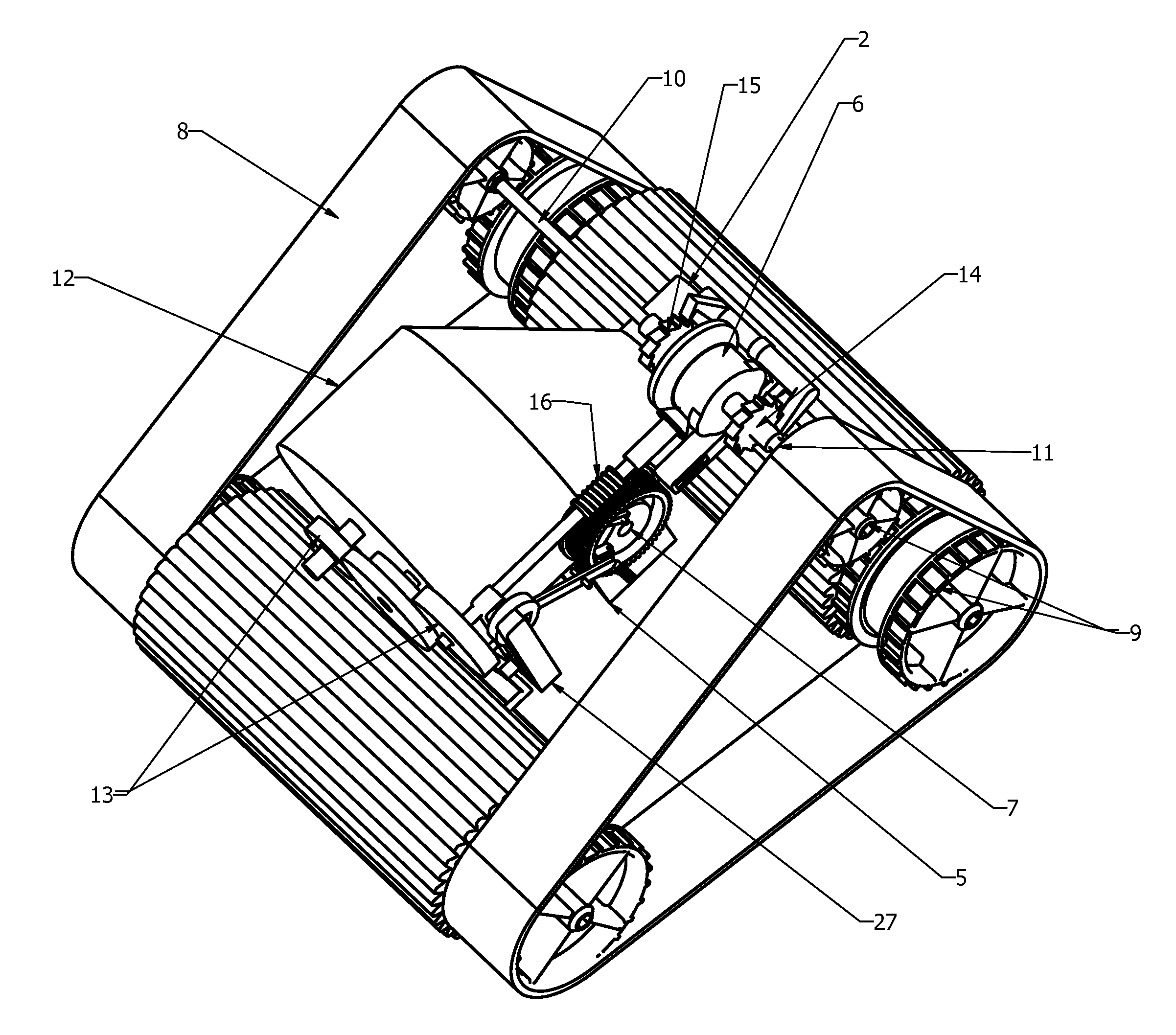
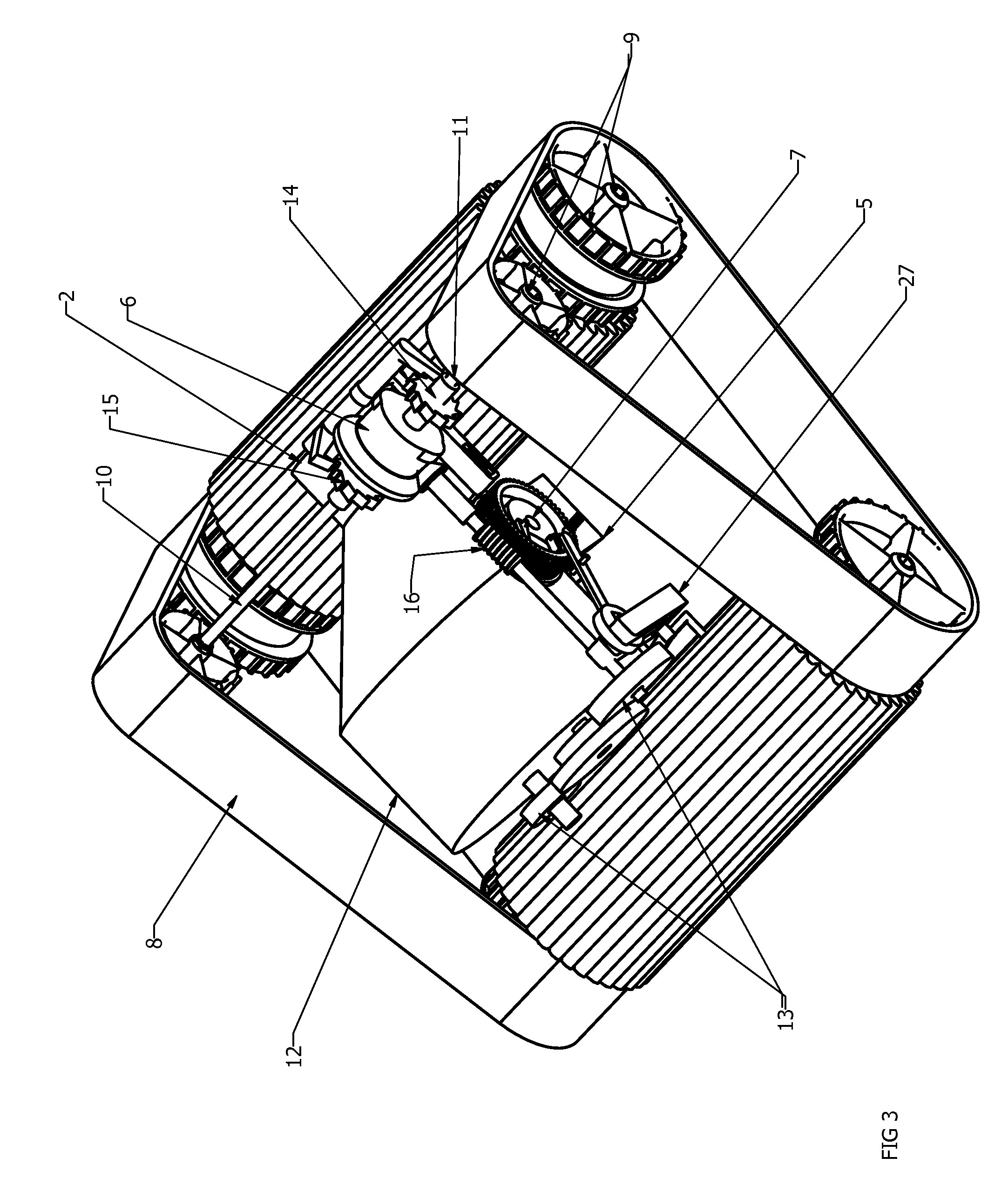
[0061]Many aspects of the invention can be better understood with the references made to the drawings below. The components in the drawings are not necessarily drawn to scale. Instead, emphasis is placed upon clearly illustrating the components of the present invention. Moreover, like reference numerals designate corresponding parts through the several views in the drawings.

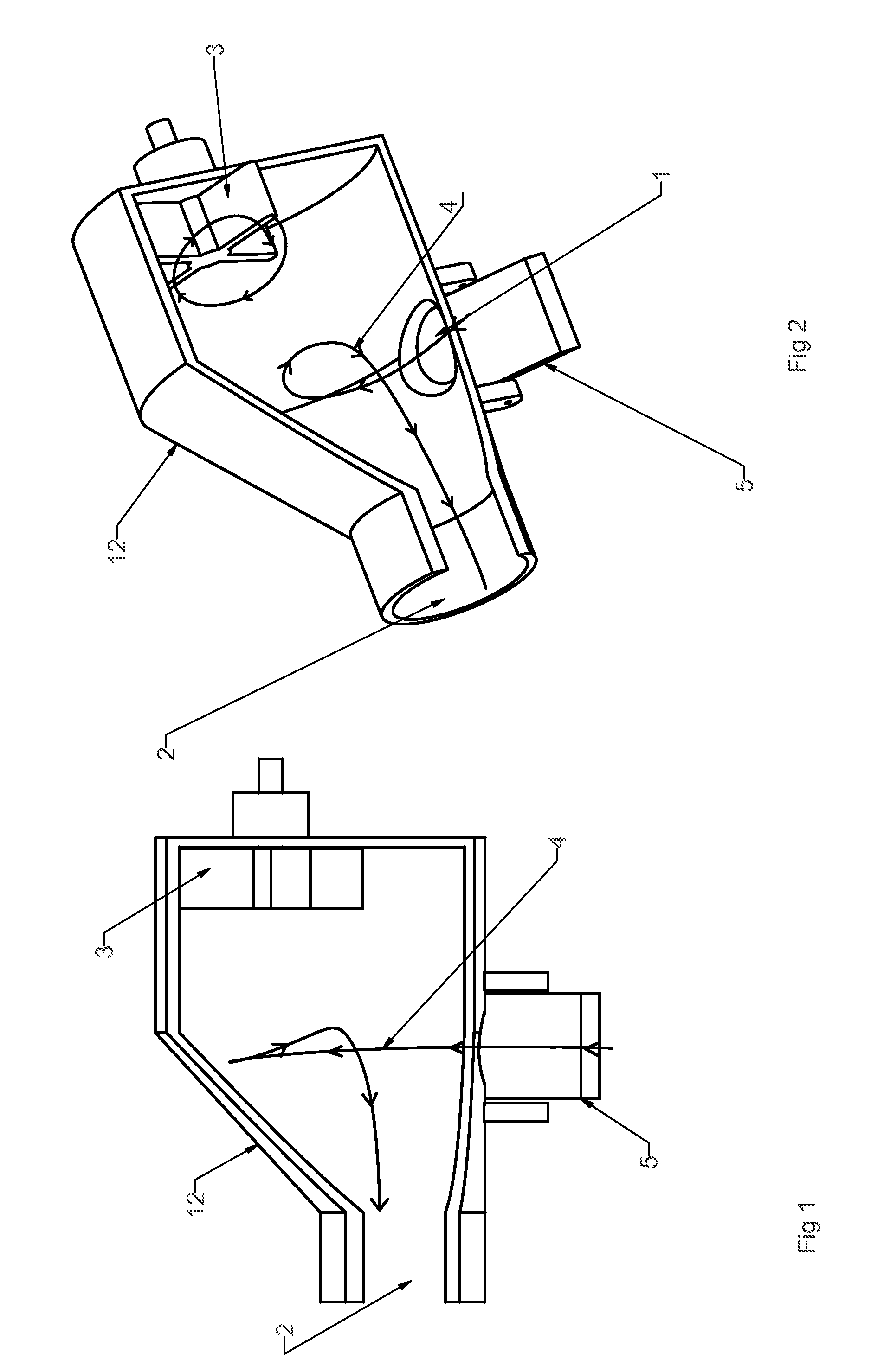
[0062]As can be seen in FIGS. 1 and 2, the inlet 1 and outlet 2 are in very close proximity to each other, with turbine 3 well away from the debris path flow, represented by line 4. The debris and flow path is shown with flow direction line and arrows.

[0063]In this configuration the angle of flow is controlled by a variable flap 5 to allow for reverse rotation of the turbine system, but it can also be fixed should other means of reverse engagement be utilized.

[0064]When suction is applied to the outlet 2, flow will enter from the inlet 1 in the direction of the arrows, and a vortex will form in the vortex chamber...


PUM


Abstract

A suction type turbine-driven pool-cleaners utilizing vortex turbines to propel and steer the pool cleaner is disclosed. The cleaner includes a housing for one or more vortex-turbine mechanisms, each with a chamber and a turbine, tracks for movement over submerged surfaces, a differential mechanism for steering purposes, a reverse of inlet flow mechanism, a cam design for engagement of steering and reversing mechanisms, a means of controller inlet flow for steering purposes, and a means of controlling flow for reversing direction of cleaner movement.

Description

CROSS REFERENCE TO RELATED APPLICATIONS[0001]This application is a continuation-in-part of PCT / IB2008 / 053718 filed Sep. 15, 2008, the entirety of which is hereby incorporated by reference.STATEMENT REGARDING FEDERALLY SPONSORED RESEARCH OR DEVELOPMENT[0002]This invention was not federally sponsored.BACKGROUND OF THE INVENTIONField of the Invention[0003]This invention relates to the general field of pool cleaners, and more specifically toward a suction type turbine-driven pool-cleaners utilizing vortex turbines to propel and steer the pool cleaner.[0004]Suction type turbine-driven pool-cleaners exists in various guises, some utilize footpads to propel them forward while others use wheels and / or tracks. Each of these cleaners have various benefits, however, they have in common a turbine that has to, at least to some extent, have at any specific interval one or more blades, or part thereof between the inlet and outlet flow channel. In other words, the turbine is in the direct path of t...

Claims


Application Information

Patent Timeline
Patent Type & Authority Patents(United States)
IPC IPC(8): E04H4/16
CPCE04H4/1654
Inventor STOLTZ, HERMAN
Owner STOLTZ HERMAN
Why Eureka
Try Eureka