Vortex turbine cleaner

Active Publication Date: 2012-03-15
STOLTZ HERMAN
View PDF3 Cites 42 Cited by
  • Summary
  • Abstract
  • Description
  • Claims
  • Application Information

AI Technical Summary

Benefits of technology

[0012]Due to the efficiency of the design, sufficient power is generated to include an optional fan unit similar to that disclosed in U.S. Pat. No. 4,168,557 to assist with down-force in slippery conditions such as tiled pool surfaces.
[0013]In a preferred embodiment, instead of using a differential, twin turbines may be inserted in the vortex chamber each providing drive to a different set of wheels or tracks. By merely applying braking force t

Problems solved by technology

In other cleaners complex gear-shift change and clutch mechanisms are used to re

Method used


Image

  • Vortex turbine cleaner
  • Vortex turbine cleaner
  • Vortex turbine cleaner

Examples


Example

[0061]Many aspects of the invention can be better understood with the references made to the drawings below. The components in the drawings are not necessarily drawn to scale. Instead, emphasis is placed upon clearly illustrating the components of the present invention. Moreover, like reference numerals designate corresponding parts through the several views in the drawings.

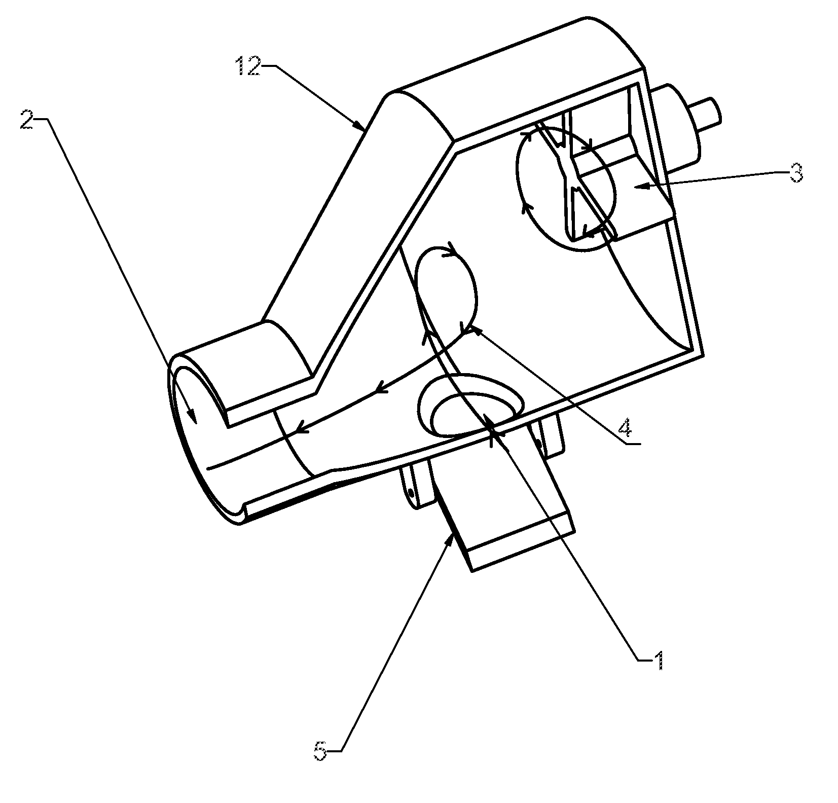
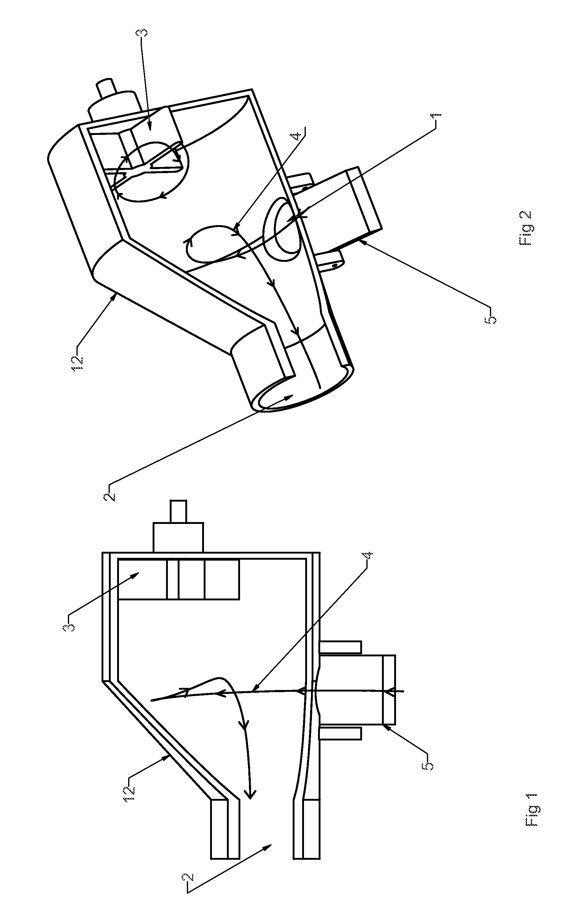
[0062]As can be seen in FIGS. 1 and 2, the inlet 1 and outlet 2 are in very close proximity to each other, with turbine 3 well away from the debris path flow, represented by line 4. The debris and flow path is shown with flow direction line and arrows.

[0063]In this configuration the angle of flow is controlled by a variable flap 5 to allow for reverse rotation of the turbine system, but it can also be fixed should other means of reverse engagement be utilized.

[0064]When suction is applied to the outlet 2, flow will enter from the inlet 1 in the direction of the arrows, and a vortex will form in the vortex chamber...


PUM


Abstract

A suction type turbine-driven pool-cleaners utilizing vortex turbines to propel and steer the pool cleaner is disclosed. The cleaner includes a housing for one or more vortex-turbine mechanisms, each with a chamber and a turbine, tracks for movement over submerged surfaces, a differential mechanism for steering purposes, a reverse of inlet flow mechanism, a cam design for engagement of steering and reversing mechanisms, a means of controller inlet flow for steering purposes, and a means of controlling flow for reversing direction of cleaner movement.

Description

CROSS REFERENCE TO RELATED APPLICATIONS[0001]This application is a continuation-in-part of PCT / IB2008 / 053718 filed Sep. 15, 2008, the entirety of which is hereby incorporated by reference.STATEMENT REGARDING FEDERALLY SPONSORED RESEARCH OR DEVELOPMENT[0002]This invention was not federally sponsored.BACKGROUND OF THE INVENTIONField of the invention[0003]This invention relates to the general field of pool cleaners, and more specifically toward a suction type turbine-driven pool-cleaners utilizing vortex turbines to propel and steer the pool cleaner.[0004]Suction type turbine-driven pool-cleaners exists in various guises, some utilize footpads to propel them forward while others use wheels and / or tracks. Each of these cleaners have various benefits, however, they have in common a turbine that has to, at least to some extent, have at any specific interval one or more blades, or part thereof between the inlet and outlet flow channel. In other words, the turbine is in the direct path of t...

Claims


Application Information

Patent Timeline
IPC IPC(8): E04H4/16
CPCE04H4/1654
Inventor STOLTZ, HERMAN
Owner STOLTZ HERMAN
Why Eureka
Try Eureka