Detachable synthetic rope connector

a synthetic rope and connector technology, applied in the direction of snap fasteners, buckles, manufacturing tools, etc., can solve the problems of insufficient allow the connection to be separated, work vessels may not have sufficient deck equipment to restrain the system, and the length of synthetic rope segments is limited, so as to increase the safety of offshore work

Inactive Publication Date: 2013-07-02
NAQUIN ANDREW +3
View PDF12 Cites 14 Cited by
  • Summary
  • Abstract
  • Description
  • Claims
  • Application Information

AI Technical Summary

Benefits of technology

[0006]The unique features of the inventive detachable synthetic rope connector allow commonly available shackles and cables to be used with pad-eyes mounted on the deck of a work vessel to handle large synthetic and other mooring components that exceed the capacity of the installed vessel deck restraint equipment. These features also increase the safety of the offshore work by providing redundancy when servicing the mooring systems. The use, function and configuration of these features for the mooring connector are embodied by the present invention.
[0007]The present invention comprises an optimized bale that is detachable from a connector body. The disconnection of the bale from the connector body allows a single connector to be separated while restraining rope under tension. The bale cross section is optimized in a manner wherein the cross section of the apex differs from the cross section of the bottom portions. Further the geometric centerline of the bale differs from a pure radius to allow optimization of the shear, bending and tension components of the stresses induced by the loading at the apex. The variation of the cross section is such that each portion is optimized for stress while minimizing weight and further allowing the passage of the bale through intended existing connecting links and chain ends. The optimization is performed to require the unique feature, in certain limits of load rating, the rotation of the bale through an intended connecting link as a means of further minimizing weight and stress for increased safety.
[0008]Other features that are desirable and embodied in the invention is the ability to reel the connector directly onto a storage reel without damaging synthetic rope. These features include external radii on all surfaces that are sufficiently large to prevent high local contact loads on the synthetic or other rope compositions. These radii are at least ½ inch in radius but may be as large as 6 inches to prevent excessive contact forces and damaging contact stresses on contacted rope on storage reels.
[0012]It is a further object that the main load pin subassembly has a main load pin with a right end and a left end, each of the ends having threaded holes, a shoulder on one of the ends configured to seat in the right or left side recess of the bale, a circular end plate on the other of the ends, configured to seat in one of the recesses of the bale and being fixed to the pin with fasteners, and the restraining load sub assembly has a main restraining pin having a right end and a left end, each of the ends fitted with padeye caps and retaining pins. Alternative to a shoulder on one end, both ends of the pin may be configured to accept circular plates each being fixed to the pin with fasteners. The radius of said fasteners being such that the plates are fixed to the pin and not to the connector body preventing torque due to relative motion of the pin with the connector body from generating high torsional loads on fasteners removing danger of loosening an end plate on the pin.

Problems solved by technology

The synthetic mooring segments have length limitations requiring that multiple segments be used in deep locations.
When large diameter synthetic mooring lines are being used, the work vessels may not have sufficiently large deck equipment to restrain the system and allow the connection to be separated.
The existing deck mounted restraint equipment is generally not large enough for the larger synthetic ropes proposed for use by the industry.

Method used


Image

  • Detachable synthetic rope connector
  • Detachable synthetic rope connector
  • Detachable synthetic rope connector

Examples


Embodiment Construction

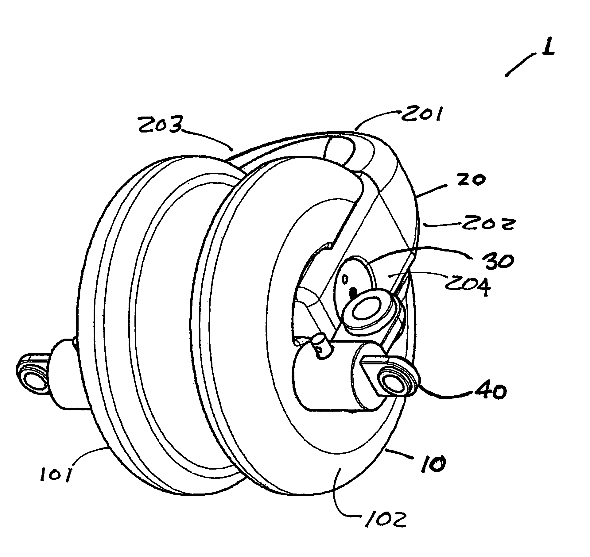
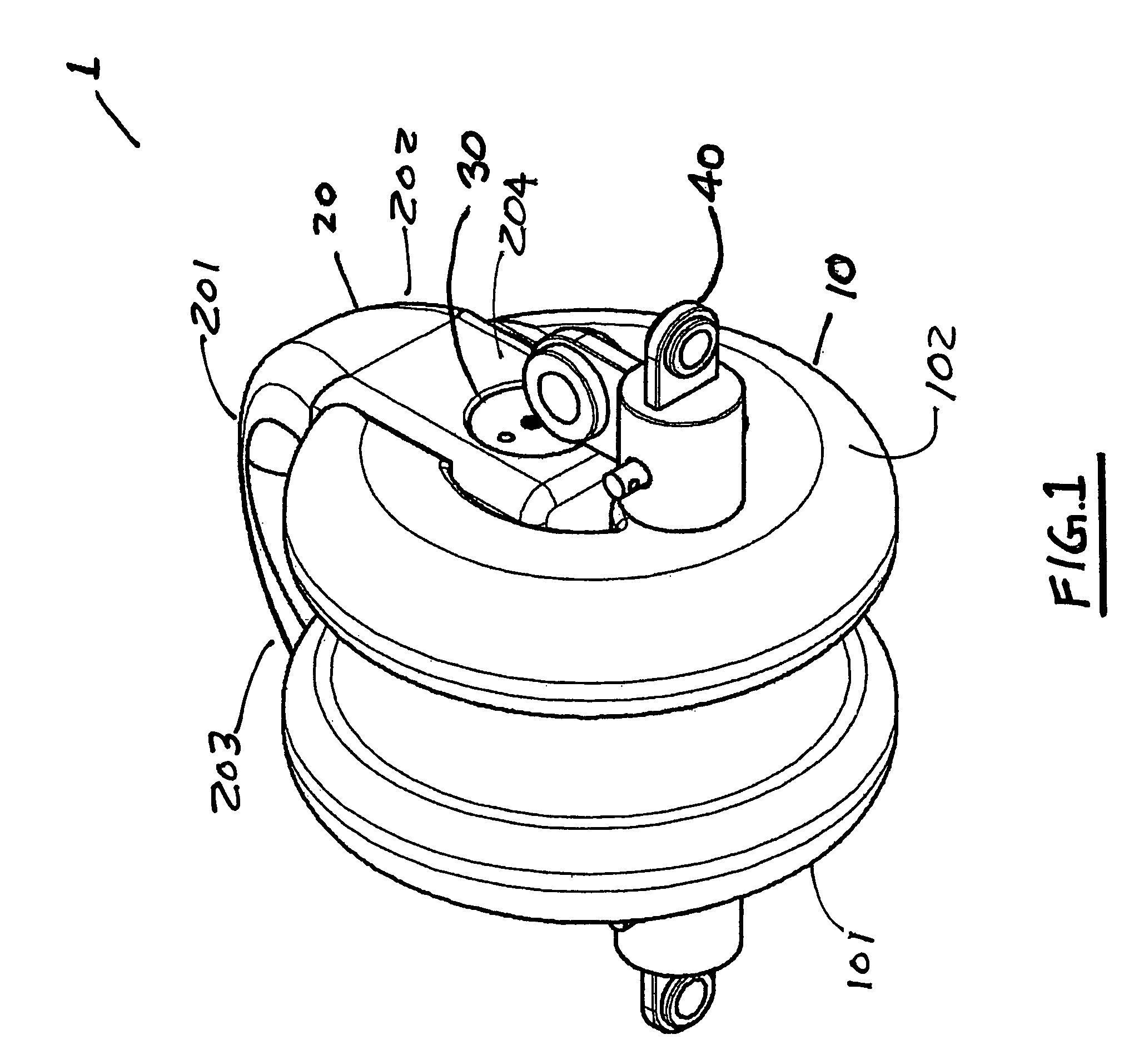
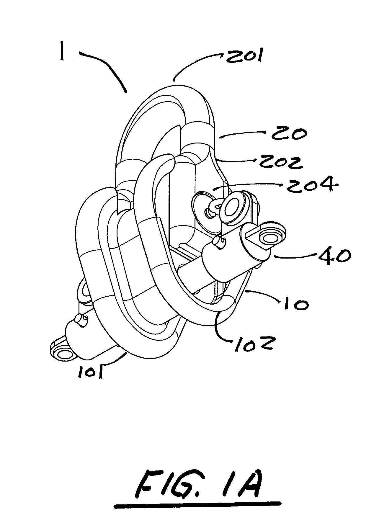
[0025]FIG. 1 presents the invention, termed a detachable rope connector 1, consisting of an assembly that includes a connector body 10 with a left side 101 and a right side 102, a bale 20 with an apex 201, a right side 202, a left side 203, a bottom right side end 204 and a bottom left side end 205, a main load pin sub assembly 30 and a restraining load sub assembly 40. FIG. 1A depicts a preferred embodiment of the inventive detachable rope connector.

[0026]The connector body 10 shown in FIGS. 3 and 3A and separate from the assembly in FIGS. 1, 1A, 2 and 2A, is formed similar to that of a conventional rope thimble from the standpoint that a synthetic rope 50 or rope of other construction, indicated in phantom lines in FIG. 2, can be wrapped around the connector body 10 and secured and thereby transfers a tension load from the rope 50 to the structure of the connector body 10.

[0027]As illustrated by the components shown in FIGS. 1, 1A, 2 and 2A, the detachable rope connector 1 transfe...


PUM

PropertyMeasurementUnit
lengthaaaaaaaaaa
tensionaaaaaaaaaa
diameteraaaaaaaaaa

Abstract

A detachable synthetic rope connector with connector body, bale, main load pin sub assembly, and a restraining load sub assembly that permits the use of large diameter synthetic and other mooring components such as cable and chain on offshore work vessels without specialized deck equipment. The inventive connector allows for safe and redundant restraint of a mooring segment in order to provide transfer of the tension load while providing connection features that simplify separation and the reduction of safety risks to vessel working personnel and the environment, and the features allow for the connector to be separated easily while the portion holding the rope is restrained while the bale can be removed.

Description

[0001]This application claims priority from U.S. Provisional application Ser. No. 61 / 215,418 (the ‘418 application’) filed May 5, 2009. The '418 application is incorporated here by reference.BACKGROUND OF THE INVENTION[0002]Offshore deepwater mooring systems frequently employ mooring segments that are synthetic. The synthetic mooring segments have length limitations requiring that multiple segments be used in deep locations. Processes of installation, moving, inspection and modifications to the mooring systems require that the segments be lifted onto an offshore work vessel and be restrained to perform the required operations.[0003]The lifting of mooring segments along with supporting anchors and seabed chain lengths above the seabed, develop significant tension due to the gravity loads. These tension levels can exceed 20 tons.[0004]Mooring segments must be separated when a winch drum or storage reel is full or when it is necessary to change or replace a connector in the mooring seg...

Claims


Application Information

Patent Timeline
Patent Type & Authority Patents(United States)
IPC IPC(8): F16G11/00
CPCB63B21/20F16G15/06Y10T24/39Y10T29/49822Y10T403/4336Y10T24/3911
Inventor NAQUIN, ANDREWHALIN, RICHARD D.HALL, RICHARD E.KAZUNAS, PETER L.
Owner NAQUIN ANDREW
Why Eureka
Try Eureka