Low capacitance container coating system and method

a low-capacity container and coating technology, applied in coatings, electrostatic spraying apparatus, electrical equipment, etc., can solve the problems of limiting the amount of electrostatic charge in the low-capacity container, affecting the overall finish and transfer efficiency, and affecting the safety of the user, so as to limit or prevent unwanted electrostatic discharge and minimize undesirable electrostatic charge storage capacity

Inactive Publication Date: 2013-07-02
NORDSON CORP
View PDF20 Cites 1 Cited by
  • Summary
  • Abstract
  • Description
  • Claims
  • Application Information

AI Technical Summary

Benefits of technology

[0006]The charge transfer material, by having an impedance to current flow or discharge, may be used not only to apply the offsetting electrostatic charge to the container, but also will prevent undesired capacitive discharges to an operator or other ground potential, during the time that the charge transfer material is coupled to the electrical energy source. In an exemplary embodiment, the charge transfer material impedance may be chosen in a range that permits offsetting charge transfer to be applied to the container, while also limiting or preventing unwanted electrostatic discharges from occurring.
[0007]By providing an offsetting electrostatic charge to the container surface, the container may be generally kept at a neutral or low residual charge potential, so that after the container is coated, the container will not capacitively hold enough charge or electrical energy to produce a discharge as the container proceeds through further finishing or processing stages. Any low residual surface charge will bleed off, such as to atmosphere, for example, so that the coated container cannot discharge to a ground potential. This benefit is attributable in part to having the support member be a low capacitance device, for example, through use of the low conductivity or semiconductive charge transfer material so that there is no capacity for holding that residual charge and allowing it to bleed off to atmosphere. Preferably, the support member contains few or no metal parts so as to minimize undesirable electrostatic charge storage capacity.
[0009]The use of semiconductive material, and optionally non-metallic material, for the charge transfer material allows for a low capacitance coating system in that the support member need not contain any materials that would allow for sufficient electrical energy storage or store capacitive charge that could produce a discharge if in close proximity to a conductive element or ground. The charge transfer member may likewise be made of low capacitance materials so that offsetting electrostatic charge may be applied to the containers being coated within a non-conductive zone or area. In this manner, the support member and the charge transfer member, and optional rotation mechanisms for rotating the work pieces, may be low capacitance to reduce the electrical energy that can be stored in the system. By also optionally using the low capacitance electrostatic spray coating device or apparatus described above, overall capacitance of the coating system may be further reduced. This promotes safety in that the operators do not need to be shielded from electrostatic shock in the system.
[0011]In another embodiment of the above method, current from the electrical energy source that is used to apply an offsetting electrostatic charge to the container during a coating operation is monitored and in response to changes in the current level, the output voltage of the electrical energy source is adjusted. In one embodiment, this adjustment may be used to prevent too much offsetting charge from being applied to the container which could otherwise cause back ionization at the surface of the container.

Problems solved by technology

Metal parts in electrostatic coating systems may allow unwanted capacitive discharges, sometimes creating a safety hazard.
During electrostatic coating operations on non-conductive and low conductivity work pieces such as glass bottles, the electrostatic process may build up electrostatic charge on the bottle which may act in effect like a capacitor because the container may not effectively be grounded.
This charge build up can have deleterious effects on the overall finish and transfer efficiency.
Thus, low conductivity containers may become self-limiting as to how much electrostatic charge can be applied to the container during an electrostatic coating operation.
The build-up of coating material on the container during a coating operation may further limit the coating process.

Method used


Image

  • Low capacitance container coating system and method
  • Low capacitance container coating system and method
  • Low capacitance container coating system and method

Examples


Embodiment Construction

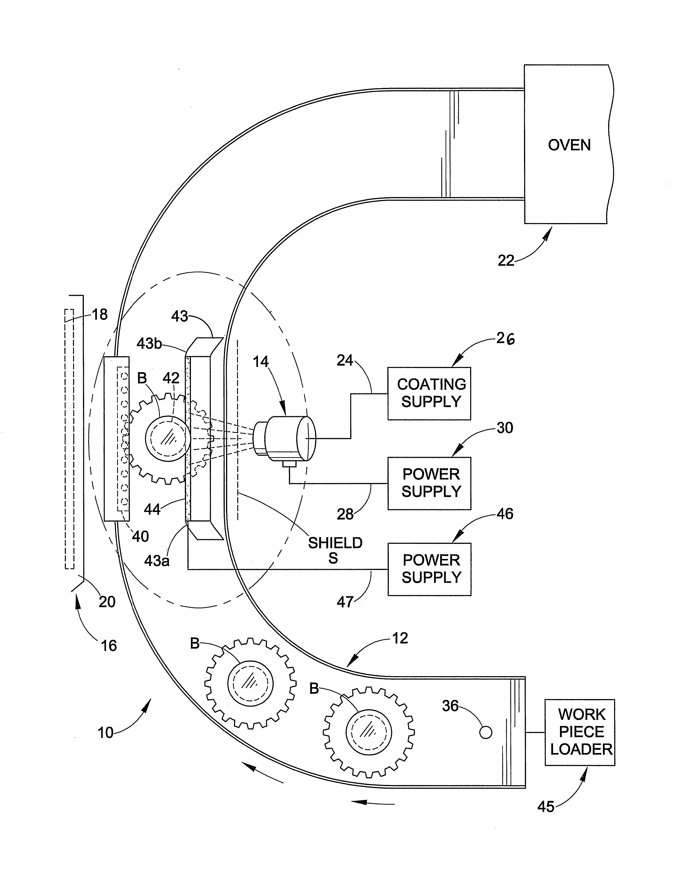
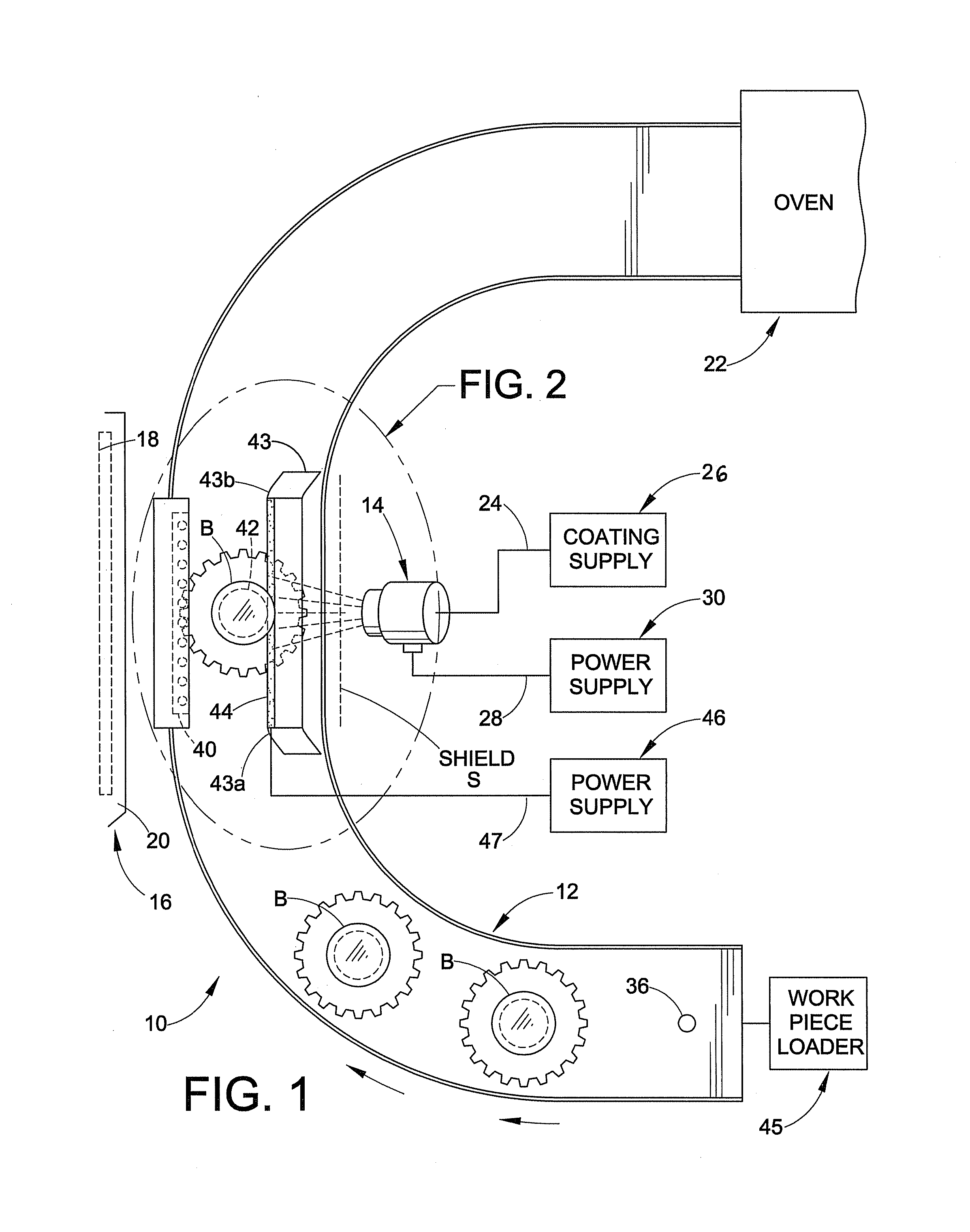
[0031]Although the various embodiments are described herein with specific reference to liquid coating of glass containers, the inventions are not limited to such specific applications. The inventions will find application to all types of coating material used for electrostatic coating of low conductivity containers, including liquid coating material and powder coating material and so on. Moreover, the inventions are not limited to any particular type, size, shape or material of non-conductive or low conductivity work pieces. The inventions will find application to many work pieces including but not limited to glass bottle and other glass containers, plastic bottles and other plastic containers and so on. An example of one type of coating is a UV coating, but the inventions are not limited to any particular coating material.

[0032]While various inventive aspects, concepts and features of the inventions may be described and illustrated herein as embodied in combination in the exemplary...


PUM


Abstract

Apparatus and method for electrostatic charging of a container for an electrostatic coating operation includes a support member for supporting a container during an electrostatic coating operation with the support member comprising a non-metallic conductive material or electrically semiconductive portion that directly contacts a surface of the container. The electrically semiconductive portion comprises non-metallic, resistive or low conductivity material and is coupled to a source of electrical energy such that the container is electrostatically charged to an opposite polarity to offset or reduce electrostatic charge build up produced by the electrostatic coating operation.

Description

TECHNICAL FIELD OF THE INVENTIONS[0001]The present disclosure relates to coating non-conductive and low conductivity containers, such as, for example but not limited to, glass bottles, with coating material such as liquid or powder. More particularly, the disclosure relates to coating low conductivity containers using electrostatic coating processes with low capacitance devices.BACKGROUND OF THE DISCLOSURE[0002]Many non-conductive or low conductivity containers have one or more coating materials applied to their outer surface. These coatings may be used as a protective layer, for example. In the past, coatings have been applied using an electrostatic process. In the case of glass bottles, for example, a metal pin has been inserted into a bottle opening with a dielectric separation between the metal pin and the bottle. Metal parts in electrostatic coating systems may allow unwanted capacitive discharges, sometimes creating a safety hazard.[0003]During electrostatic coating operations...

Claims


Application Information

Patent Timeline
Patent Type & Authority Patents(United States)
IPC IPC(8): B05C5/00B05C5/02H05C1/00
CPCB05B5/082B05D1/04B05B5/08B05B5/087B05B5/084
Inventor FULKERSON, TERRENCE M.WILSON, TIMOTHY E.BORDNER, MICHAEL A.DAVISSON, JONSYROWSKI, BRAD M.
Owner NORDSON CORP
Why Eureka
Try Eureka