Capacitively coupled connector for flexible printed circuit applications

a flexible printed circuit and connector technology, applied in printed circuits, printed circuit details, high frequency circuit adaptations, etc., can solve the problems of high manufacturing cost, over-all size of these devices, etc., and achieve the effect of reducing height and siz

Active Publication Date: 2013-07-02
MOLEX INC
View PDF18 Cites 4 Cited by
  • Summary
  • Abstract
  • Description
  • Claims
  • Application Information

AI Technical Summary

Benefits of technology

[0004]It is a general object of the Present Invention to provide an improved FPC connector of reduced height and size which utilizes capacitive coupling to effect signal transmission between the signal transmission conductors on an extent of FPC and the contacts of a circuit board.
[0005]Another object of the Present Invention is to provide a connector for connecting a length of FPC to a plurality of contacts on a circuit board, wherein the connector includes a housing having an opening formed therein that receives the mating end of a length of FPC, the housing being mountable to a circuit board and the housing opening encompassing a plurality of contact pads disposed on a surface of the circuit board, the housing including means for retaining the end of the FPC in the opening and means for exerting a pressing force down on the end of the FPC, the FPC further including a dielectric barrier disposed on its conductors that prevent galvanic electrical contact from occurring between the FPC conductors and the circuit board contacts, but permits signal transmission therethrough by way of capacitive coupling.
[0006]A further object of the Present Invention is to provide an FPC connector that does not utilize a moveable actuator, but rather utilizes simple insertion movement into a receptacle and the receptacle providing a downward pressure to supply a sufficient contact pressure.
[0007]A still further object of the Present Invention is to provide a connector for connecting a length of FPC to a circuit board that does not use metal terminals and which is relatively easy to manufacture, is of low cost and of reduced height.

Problems solved by technology

The industry seeks to reduce the overall size of these devices and FPC connectors, although they can be made small, they are usually expensive and complex to manufacture because they require a movable actuator to force the FPC into contact with the metal terminals of the connector.

Method used


Image

  • Capacitively coupled connector for flexible printed circuit applications
  • Capacitively coupled connector for flexible printed circuit applications
  • Capacitively coupled connector for flexible printed circuit applications

Examples


Embodiment Construction

[0027]While the Present Invention may be susceptible to embodiment in different forms, there is shown in the Figures, and will be described herein in detail, specific embodiments, with the understanding that the disclosure is to be considered an exemplification of the principles of the Present Invention, and is not intended to limit the Present Invention to that as illustrated.

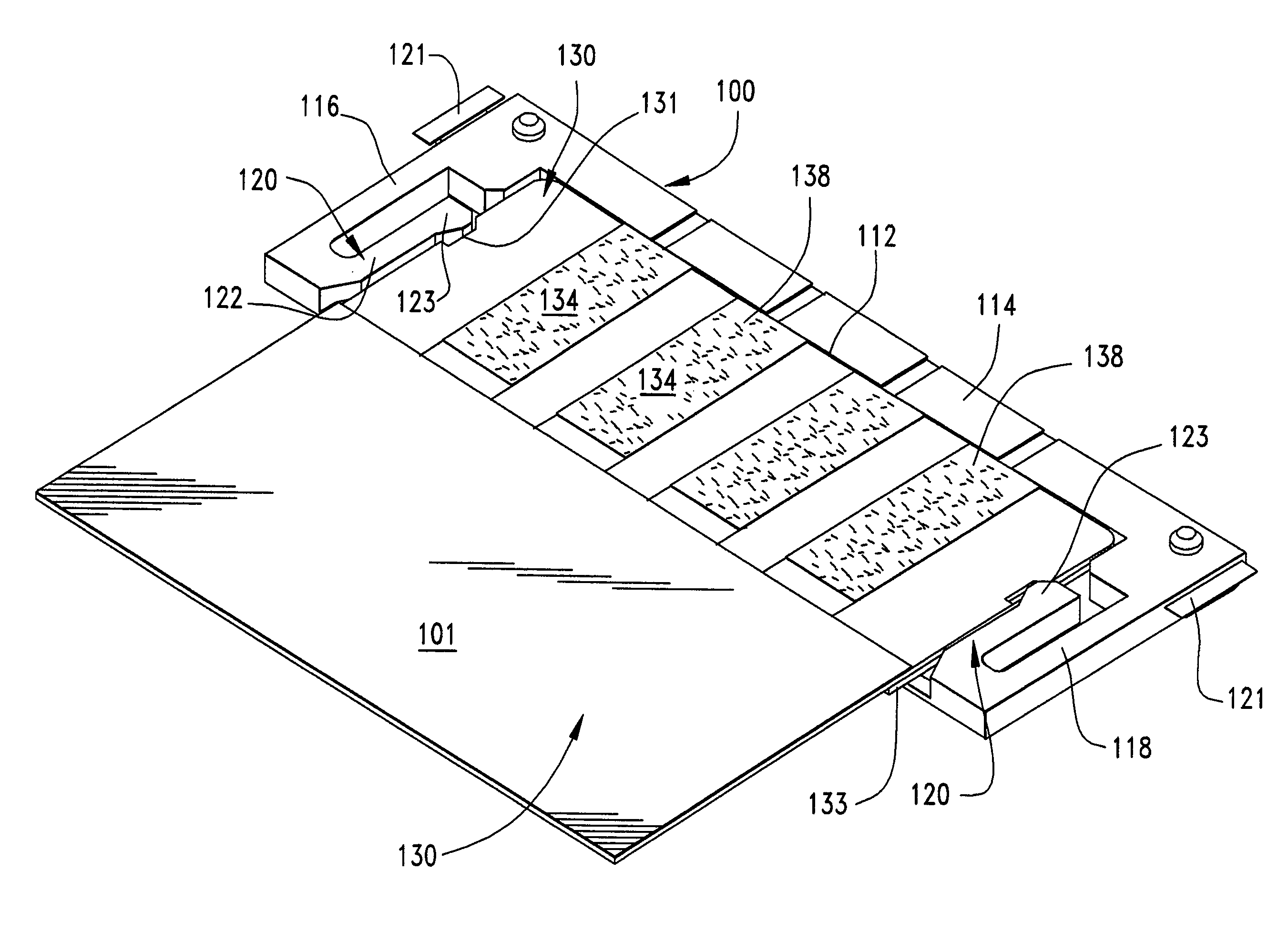
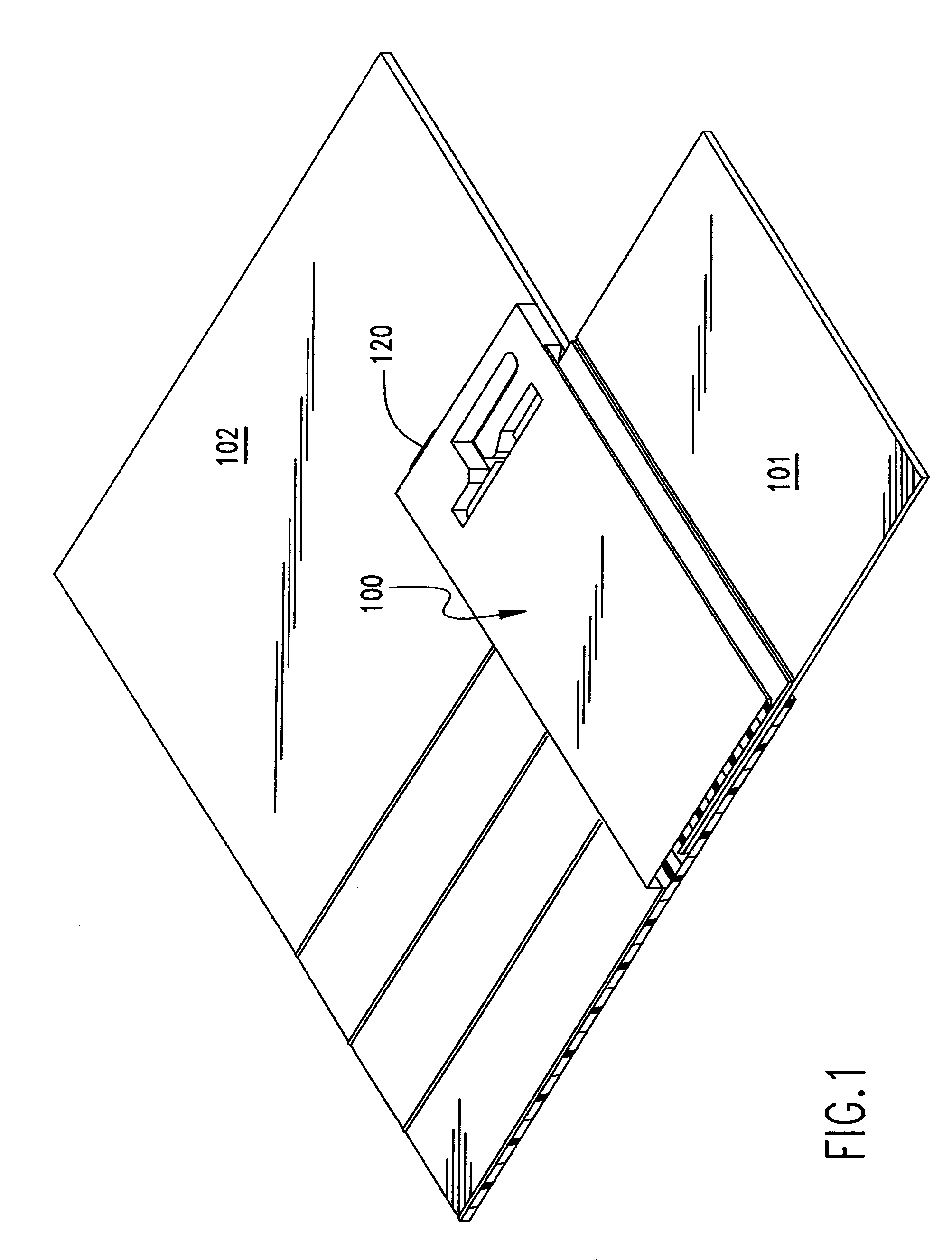
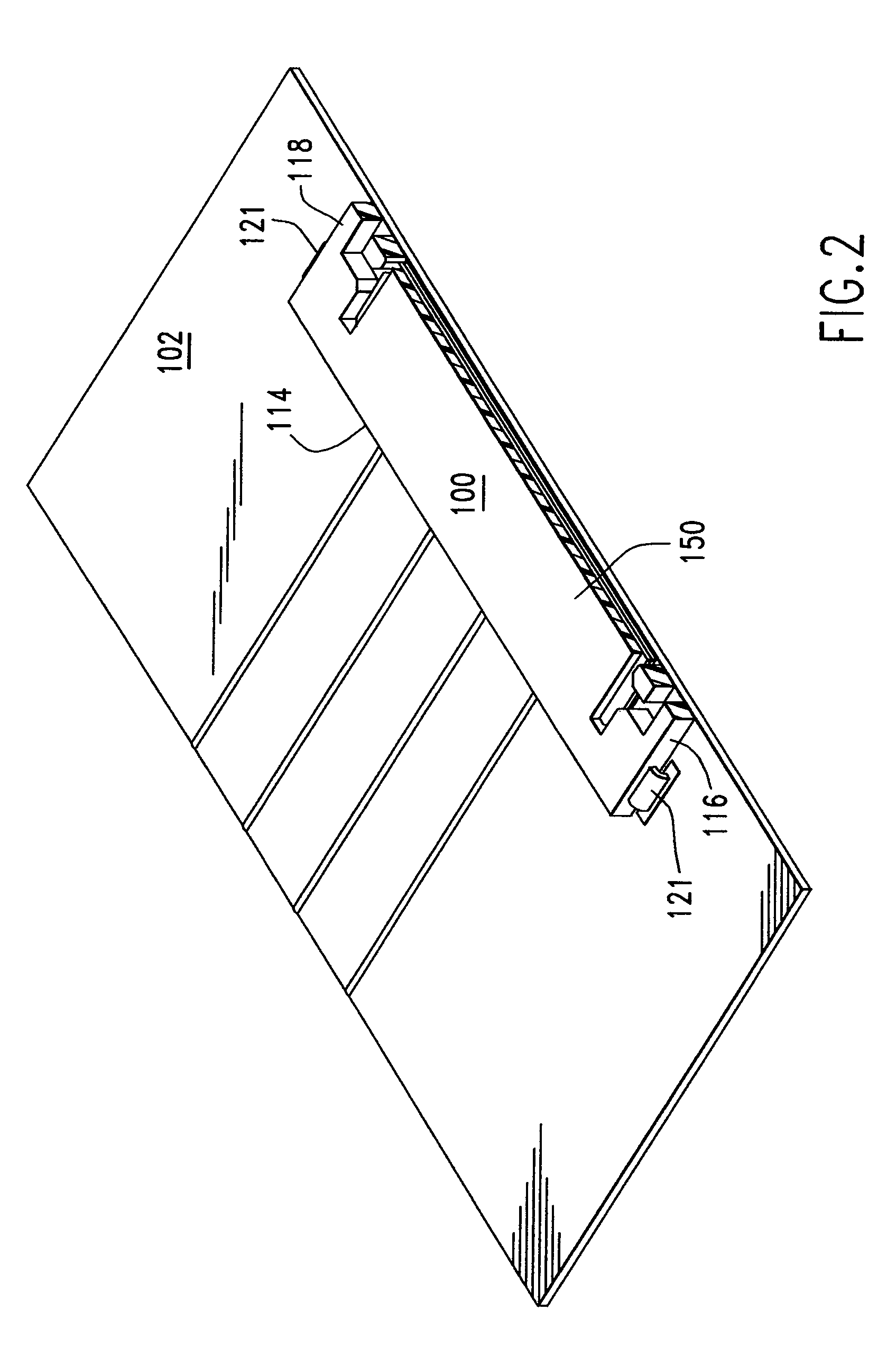
[0028]The Present Invention is preferably directed to connector 100 used for mounting FPC 101 to circuit board 102, having distinct mounting area 103 (as illustrated in FIG. 7) defined thereon with a plurality of conductive surfaces, typically in the form of contact pads 104. In a preferred embodiment, connector 100 has U-shaped insulative housing 110 having a central opening or receptacle portion 112, cooperatively defined by base portion 114 and two spaced apart leg portions 116, 118. Central opening 112 forms the center part of the “U” shape, and the receptacle portion of connector 100. Housing 110 may incl...


PUM


Abstract

A FPC connector has an insulative housing with a general U-shape that defines an opening that receives a free end of a length of FPC. The housing has a base and two leg portions and the leg portions have engagement arms that hold engage the FPC free end when inserted into the connector housing opening. A cover of the connector housing has press members that press the FPC and dielectric barriers thereon into contact with contacts on a circuit board.

Description

BACKGROUND OF THE INVENTION[0001]The Present Invention is generally directed to flexible printed circuit (“FPC”) style connectors, and more particularly to an FPC connector that utilizes a capacitive-coupling conductor mating interface to obtain a significantly reduced overall height.[0002]FPC connectors are used in many electronic devices. The industry seeks to reduce the overall size of these devices and FPC connectors, although they can be made small, they are usually expensive and complex to manufacture because they require a movable actuator to force the FPC into contact with the metal terminals of the connector.[0003]Accordingly, the Present Invention is directed to an improved FPC connector that overcomes the aforementioned disadvantages and presents reduced height, size and cost opportunities and which does not utilize conductive terminals.SUMMARY OF THE INVENTION[0004]It is a general object of the Present Invention to provide an improved FPC connector of reduced height and ...

Claims


Application Information

Patent Timeline
Patent Type & Authority Patents(United States)
IPC IPC(8): H01R12/00
CPCH05K1/147H05K3/365H05K1/0239H05K1/118H05K2201/2018
Inventor NIITSU, TOSHIHIRONAGASAWA, HIDEO
Owner MOLEX INC
Why Eureka
Try Eureka