Rotary compressor

a compressor and rotary technology, applied in the field of compressors, can solve the problems of increasing the size of the eccentric and its corresponding counterweight, and the design and assembly of such a compressor becoming more difficult, so as to maintain the balance, and reduce the load of the bearing

Inactive Publication Date: 2011-03-31
TECUMSEH PROD CO
View PDF9 Cites 4 Cited by
  • Summary
  • Abstract
  • Description
  • Claims
  • Application Information

AI Technical Summary

Benefits of technology

[0007]The present invention relates to compressors and, particularly, to rotary compressors. In one exemplary embodiment, the eccentric on the crankshaft of a rotary compressor, as well as the roller that surrounds the eccentric, is replaced by an elongated, preferably elliptical, cam that acts as a double eccentric. In this manner, the elliptical cam provides for inherent balancing of the crankshaft and other components of the compressor, eliminating the need to use counterweights. Specifically, the elliptical cam is symmet...

Problems solved by technology

However, as the size of the rotary compressor increases, the size of the eccentric and its corresponding counterweight also ...

Method used


Image

  • Rotary compressor
  • Rotary compressor
  • Rotary compressor

Examples


Embodiment Construction

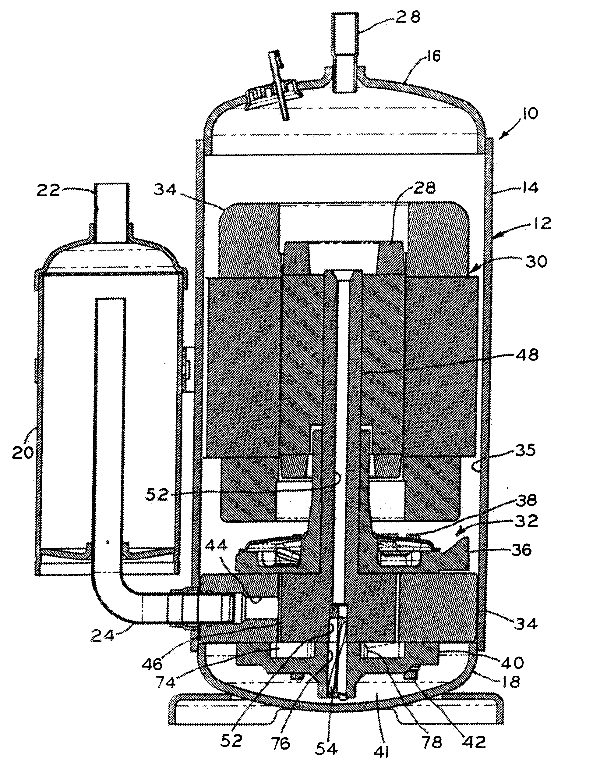
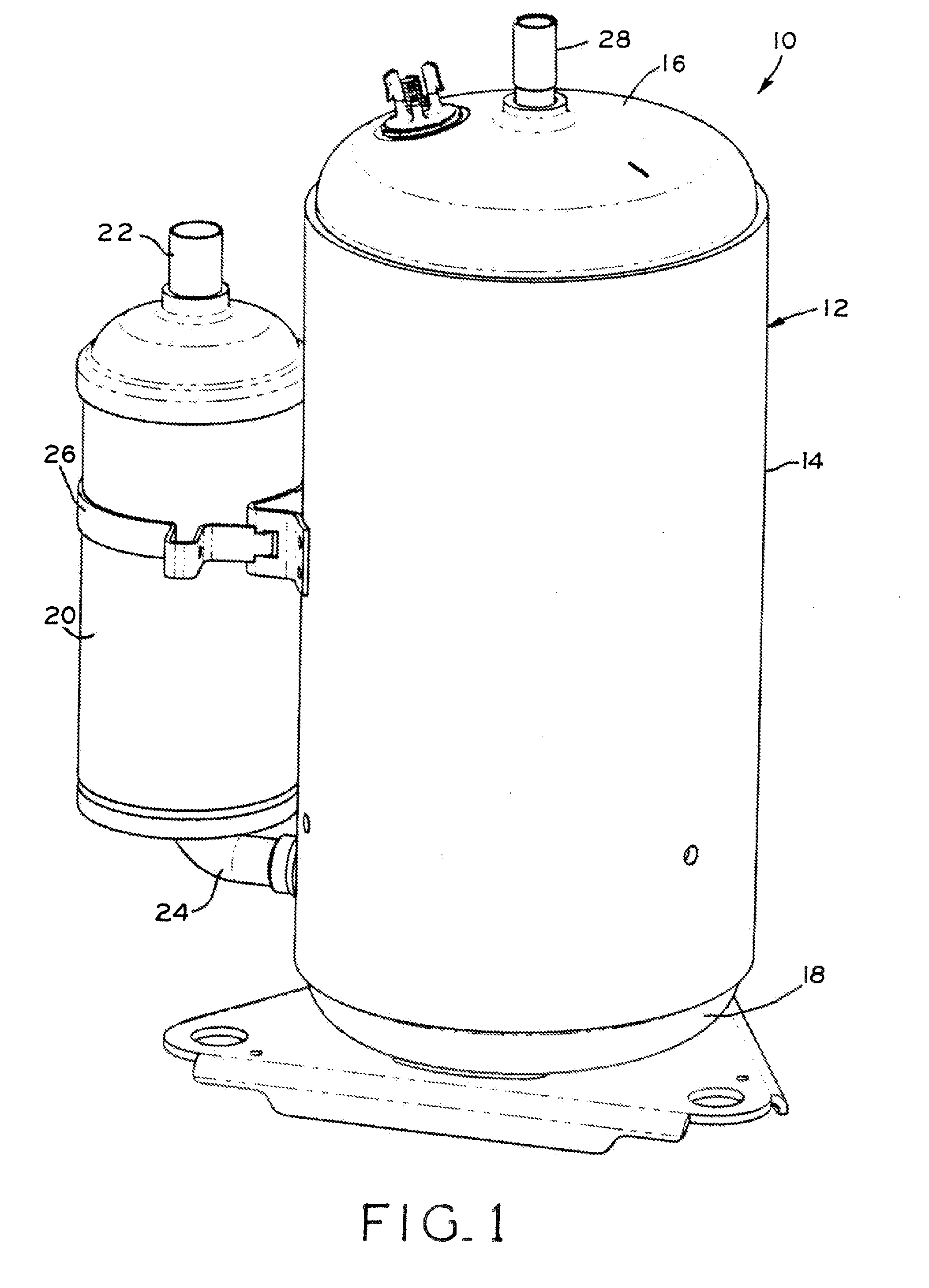
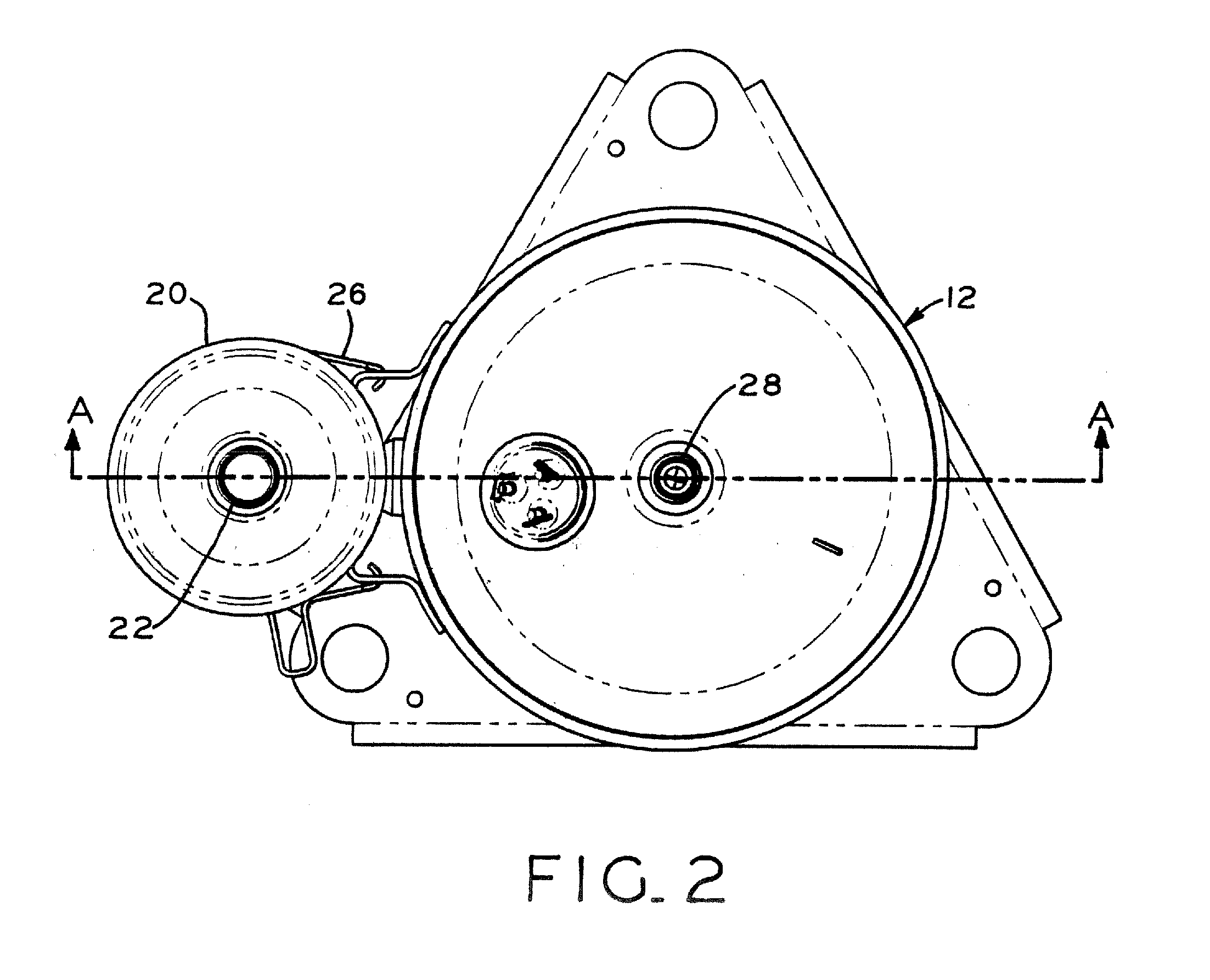
[0024]FIG. 1 illustrates the rotary compressor 10 forming one embodiment of the present invention. Compressor 10 includes an outer hermetic housing 12 including center portion 14 to which upper and lower caps 16 and 18 are connected, such as by welding. A conventional suction accumulator 20 having inlet 22 and outlet suction line 24 is connected to the center portion 14 of compressor 10 by means of mounting strap 26. Compressed refrigerant is discharged from high pressure housing 12 through discharge line 28. Compressor 10 may be a component of a heating and / or cooling circuit and functions to compress the working fluid, such as a refrigerant, which may be a hydrofluorocarbon, chlorofluorocarbon, hydrochlorofluorocarbon, or carbon dioxide refrigerant, for example.

[0025]Turning now to FIGS. 3-5, motor 30 and compression mechanism 32 are mounted within hermetic housing 12. Oil sump 41 (FIG. 3) is formed in the lower portion of hermetic housing 12. The motor includes stator 34 and roto...


PUM


Abstract

The eccentric on the crankshaft of a rotary compressor, as well as the roller that surrounds the crankshaft, is replaced by an elliptical cam that acts as a double eccentric. In this manner, the elliptical cam provides for proper balancing of the crankshaft and other components of the compressor, while eliminating the need to use counterweights. Specifically, the elliptical cam is symmetrical, resulting in equal forces acting on opposing sides of the elliptical cam. This allows the elliptical cam to maintain its balance throughout its rotation, even when operating at a high rate of revolution.

Description

CROSS-REFERENCE TO RELATED APPLICATION[0001]This application claims the benefit under Title 35, U.S.C. §119(e) of U.S. Provisional Patent Application Ser. No. 61 / 246,319, filed Sep. 28, 2009, titled ROTARY COMPRESSOR, the disclosure of which is expressly incorporated herein by reference.BACKGROUND[0002]1. Field of the Invention[0003]The present invention relates to compressors and, particularly, to rotary compressors.[0004]2. Description of the Related Art[0005]In a rotary compressor, the compression mechanism includes an eccentric positioned within a cylindrical compression chamber. A vane extending from the cylindrical wall of the compression chamber contacts a roller positioned around the eccentric and divides the compression chamber into compression and suction pockets. As the eccentric and, correspondingly, the roller move through the compression chamber, the compression pocket decreases in volume to compress a working fluid contained therein. At the same time, the suction pock...

Claims


Application Information

Patent Timeline
IPC IPC(8): F04B35/04
CPCF04C18/356F04C29/0042F04C23/008
Inventor COFFEY, DONALD L.LENZ, JAMES R.
Owner TECUMSEH PROD CO
Why Eureka
Try Eureka