Image processing method, image processing apparatus, image forming apparatus, image forming system, and storage medium

a technology of image processing and forming apparatus, applied in the direction of electrical apparatus, printing, pictoral communication, etc., can solve the problems of liquid-jet head inkjet failure, ink-jet head failure, ink-jet head failure, etc., to and reduce the droplet size

Inactive Publication Date: 2013-07-09
RICOH KK
View PDF25 Cites 2 Cited by
  • Summary
  • Abstract
  • Description
  • Claims
  • Application Information

AI Technical Summary

Benefits of technology

[0030]Aspects of the present invention provide an image processing method, an image processing apparatus, an image forming apparatus, an image forming system, and a storage medium that solve or reduce one or more problems caused by the limitations and disadvantages of the related art.
[0031]An aspect of the present invention provides a method of processing image data for an image forming apparatus for forming an image on a recording medium using a recording head including multiple nozzles for jetting ink droplets. The method includes a conversion step of converting multilevel data of the image into a dot pattern using a multilevel error diffusion process supporting n gradation levels (n≧2). The conversion step includes the steps of determining a pixel corresponding to an abnormal nozzle incapable of correctly jetting droplets onto the recording medium or incapable of jetting droplets of a particular droplet size based on abnormal nozzle information provided for each of droplet sizes supported by the nozzles; preventing jetting of a droplet onto the determined pixel corresponding to the abnormal nozzle; distributing a quantization error of the determined pixel calculated in the multilevel error diffusion process to neighboring pixels; and if extra-large droplets with a droplet size greater than the droplet size of a full-size droplet capable of filling a pixel are to be formed in the neighboring pixels as a result of distributing the quantization error, removing one or more of the extra-large droplets or reducing the droplet size of one or more of the extra-large droplets.
[0032]Another aspect provides an image processing apparatus for processing image data for an image forming apparatus for forming an image on a recording medium using a recording head including multiple nozzles for jetting ink droplets. The apparatus includes a control unit configured to convert multilevel data of the image into a dot pattern using a multilevel error diffusion process supporting n gradation levels (n≧2). The control unit is configured to determine a pixel corresponding to an abnormal nozzle incapable of correctly jetting droplets onto the recording medium or incapable of jetting droplets of a particular droplet size based on abnormal nozzle information provided for each of droplet sizes supported by the nozzles; to prevent jetting of a droplet onto the determined pixel corresponding to the abnormal nozzle; to distribute a quantization error of the determined pixel calculated in the multilevel error diffusion process to neighboring pixels; and if extra-large droplets with a droplet size greater than a droplet size of a full-size droplet capable of filling a pixel are to be formed in the neighboring pixels as a result of distributing the quantization error, to remove one or more of the extra-large droplets or reduce the droplet size of one or more of the extra-large droplets.
[0033]Another aspect provides an image forming system including an image forming apparatus configured to form an image on a recording medium using a recording head including multiple nozzles for jetting ink droplets. The image forming apparatus includes a control unit configured to convert multilevel data of the image into a dot pattern using a multilevel error diffusion process supporting n gradation levels (n≧2). The control unit is configured to determine a pixel corresponding to an abnormal nozzle incapable of correctly jetting droplets onto the recording medium or incapable of jetting droplets of a particular droplet size based on abnormal nozzle information provided for each of droplet sizes supported by the nozzles; to prevent jetting of a droplet onto the determined pixel corresponding to the abnormal nozzle; to distribute a quantization error of the determined pixel calculated in the multilevel error diffusion process to neighboring pixels; and if extra-large droplets with a droplet size greater than a droplet size of a full-size droplet capable of filling a pixel are to be formed in the neighboring pixels as a result of distributing the quantization error, to remove one or more of the extra-large droplets or reduce the droplet size of one or more of the extra-large droplets.

Problems solved by technology

Meanwhile, an inkjet head used as a liquid-jet head sometimes develops a problem called “ink-jetting failure” where a nozzle of the inkjet head becomes unable to jet ink droplets (such a nozzle is called a “failed nozzle”).
The ink-jetting failure occurs, for example, because of dust entered into a nozzle during manufacturing, degradation of a nozzle due to long-term use, or degradation of a device for causing ink ejection.
Particularly, ink-jetting failure due to degradation of a device for causing ink ejection may randomly occur during the service life of an inkjet recording apparatus.
However, in current inkjet recording apparatuses where the number of nozzles on each recording head has been increased as described above to improve the recording speed, the problem of abnormal nozzles are not negligible.
For example, manufacturing high-quality recording heads including no abnormal nozzle or designed to prevent occurrence of abnormal nozzles require higher production costs which lead to higher prices of the recording heads.
Abnormal nozzles may cause defects such as a white stripe in an image.
Accordingly, with one-pass recording, it is not possible to fill or cover (make inconspicuous, obscure, or conceal) a blank in an image caused by ink-jetting failure using a normal nozzle as in multiscan recording.
Also, even with multiscan recording, there are cases where it is difficult to fill a blank caused by abnormal nozzles due to the positions and / or number of the abnormal nozzles.
For example, in a multiscan recording mode where the number of passes is comparatively small, nozzles usable as substitutes for abnormal nozzles are limited and the workload of the substitute nozzles increases.
Also, in some cases, substitute nozzles may not be available due to characteristics of the recording head or drive waveform design.
However, even the correction method disclosed by patent documents 3 through 7 is not applicable to all situations.
For example, image data that can be increased in density are not always available near unfilled pixels corresponding to an abnormal nozzle.
Also, increasing the density of only pixels in the very vicinity of the unfilled pixels may increase the granularity.
This in turn may reduce the quality of an image.
However, since the degree of penetration of an ink into a recording medium varies depending on the absorption characteristics of the ink and the recording medium, using droplets with such a large droplet size (or a large amount of ink) may in some cases cause bleeding and reduce the quality of an edge portion (or at a color boundary) of an image and may also affect color development.
Such problems caused by excessive amount of ink are side effects (secondary problems) caused by a correction process performed to cover a white stripe.
Thus, the above related-art method employing the multilevel error diffusion process may cause such side effects.

Method used


Image

  • Image processing method, image processing apparatus, image forming apparatus, image forming system, and storage medium
  • Image processing method, image processing apparatus, image forming apparatus, image forming system, and storage medium
  • Image processing method, image processing apparatus, image forming apparatus, image forming system, and storage medium

Examples


Embodiment Construction

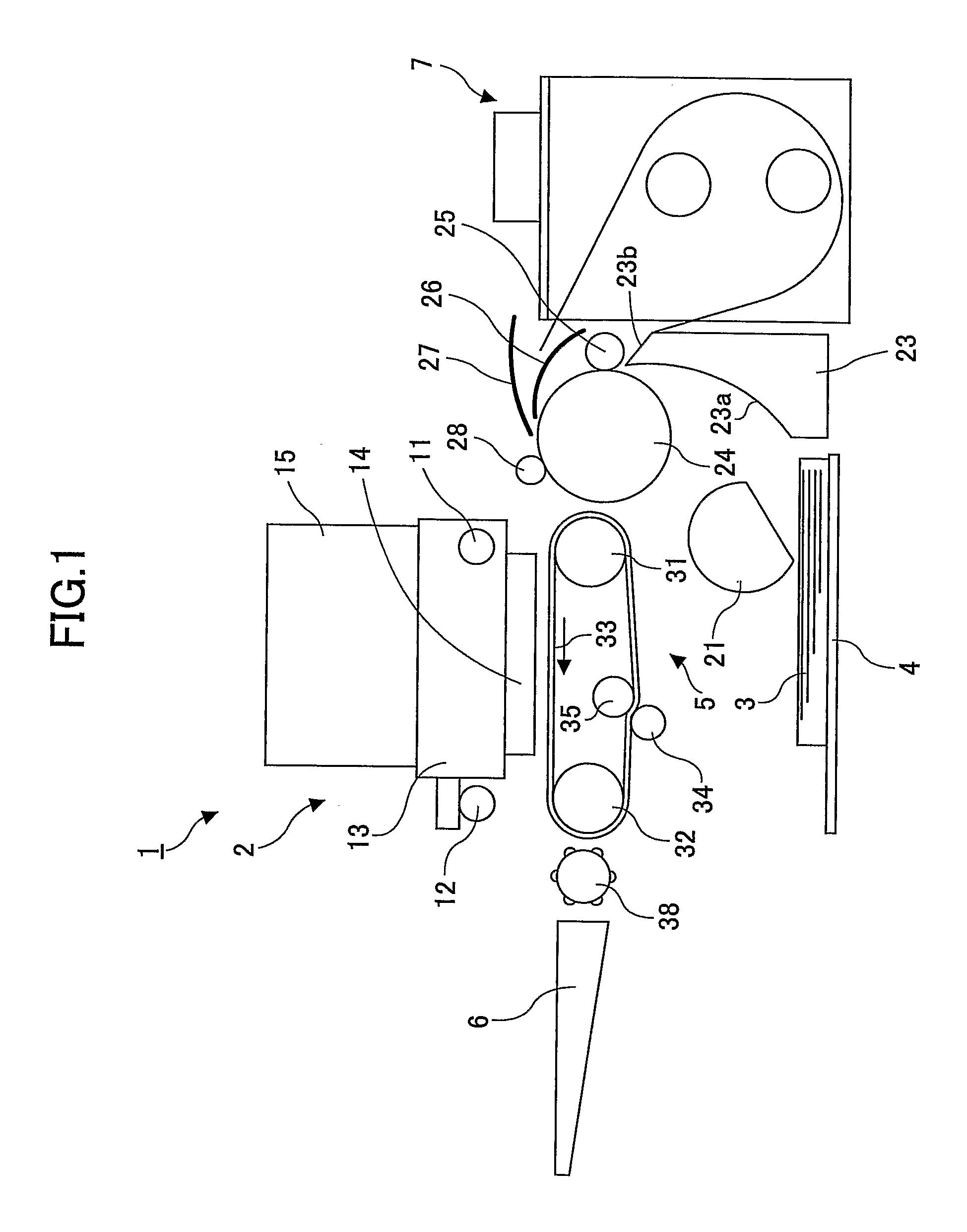
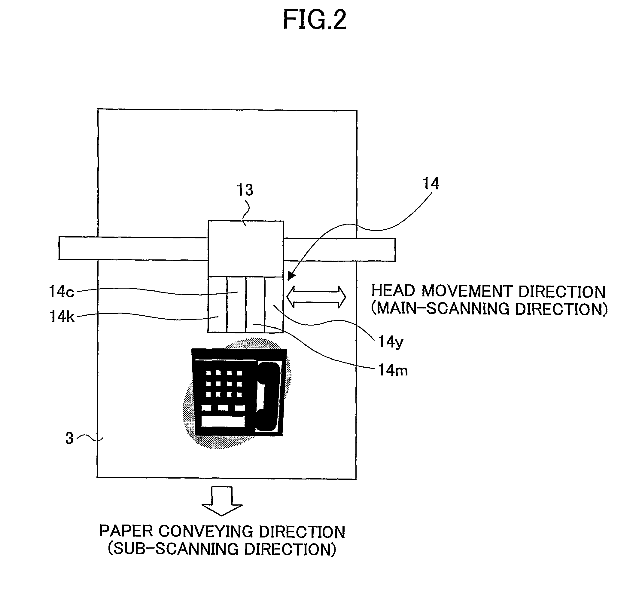
[0065]Preferred embodiments of the present invention are described below with reference to the accompanying drawings. An inkjet recording apparatus used as an example of an image forming apparatus according to an embodiment of the present invention is described below with reference to FIGS. 1 through 4. FIG. 1 is a schematic diagram of mechanical parts of the inkjet recording apparatus; FIG. 2 is a plan view of the mechanical parts; FIG. 3 is a perspective view of a head unit of the inkjet recording apparatus; and FIG. 4 is a schematic diagram of a conveyor belt of the inkjet recording apparatus.

[0066]The inkjet recording apparatus includes a main unit 1 including an image forming unit 2, and a paper-feed tray 4 disposed below the main unit 1 and capable of holding multiple recording media 3 (hereafter called paper 3). The paper 3 is fed from the paper-feed tray 4 into a conveying mechanism 5. The image forming unit 2 forms an image on the paper 3 being conveyed by the conveying mec...


PUM


Abstract

An image processing method includes converting multilevel data of an image into a dot pattern using a multilevel error diffusion process. The conversion includes determining a pixel corresponding to an abnormal nozzle based on abnormal nozzle information provided for each of droplet sizes supported by nozzles of an image forming apparatus; preventing jetting of a droplet onto the determined pixel; distributing a quantization error of the determined pixel calculated in the multilevel error diffusion process to neighboring pixels; and if extra-large droplets with a droplet size greater than the droplet size of a full-size droplet capable of filling a pixel are to be formed in the neighboring pixels as a result of distributing the quantization error, removing one or more of the extra-large droplets or reducing the droplet size of one or more of the extra-large droplets.

Description

TECHNICAL FIELD[0001]A certain aspect of the present invention relates to an image processing method, an image processing apparatus, an image forming apparatus, an image forming system, and a storage medium.BACKGROUND ART[0002]A liquid-jet image forming apparatus such as an inkjet recording apparatus uses one or more recording heads for jetting ink droplets to form an image. A liquid-jet image forming apparatus is used, for example, for a printer, a facsimile machine, a copier, a plotter, or a multifunction copier having functions of them. Such a liquid-jet image forming apparatus jets ink droplets from its recording heads onto paper and thereby forms (records or prints) an image on the paper. There are roughly two types of liquid-jet image forming apparatuses: a serial-type image forming apparatus including a recording head that jets ink droplets while moving in the main-scanning direction to form an image; and a line-type image forming apparatus including a line-type recording hea...

Claims


Application Information

Patent Timeline
Patent Type & Authority Patents(United States)
IPC IPC(8): B41J29/38
CPCB41J2/2132B41J2/2139B41J2/16579H04N1/4052H04N1/409H04N1/40087
Inventor HIRANO, MASANORI
Owner RICOH KK
Why Eureka
Try Eureka