Devices, systems, and methods for percutaneous trans-septal left atrial appendage occlusion

a technology of appendage occlusion and percutaneous transseptal, which is applied in the field of devices, systems and methods for percutaneous transseptal left atrial appendage occlusion, can solve the problems of difficult dose of warfarin, high stroke risk of half of patients, and long-term use of anti-coagulation treatments

Active Publication Date: 2013-07-09
CVDEVICES
View PDF10 Cites 19 Cited by
  • Summary
  • Abstract
  • Description
  • Claims
  • Application Information

AI Technical Summary

Benefits of technology

[0009]In another embodiment, the second device further comprises a shaft having a distal end, wherein the loop is coupled to the shaft at or near the distal end of the shaft. In yet another embodiment, at least one aperture is defined within the first tube at or near the balloon, the at least one aperture sized and shaped to allow a gas and / or a liquid to be introduced and / or removed from the balloon. In an additional embodiment, the balloon of the first device, when inserted into an atrial appendage cavity, is capable of inflation to displace blood present within the atrial appendage cavity. In yet an additional embodiment, the balloon of the first device, when positioned at an entrance of an atrial appendage cavity, is capable of inflation to occlude the entrance of the atrial appendage cavity, and wherein suction from a suction source operably coupled to the first tube facilitates the removal of blood present within the atrial appendage cavity.
[0014]In at least one method for occluding an atrial appendage of a heart of a patient, the method comprises the steps of introducing at least a portion of a first device into an entrance of an atrial appendage cavity, the first device comprising a first tube having a proximal end and a distal end and a balloon capable of inflation and deflation, the balloon coupled to the first tube at or near the distal end of the first tube, introducing at least a portion of a second device into a pericardial space surrounding the heart, the second device comprising a second tube sized and shaped for insertion into the pericardial space surrounding the heart, the second tube comprising a lumen extending at least partially from a second tube distal end to a second tube proximal end and a loop sized and shaped to fit at least partially within the lumen of the second tube, wherein the loop is capable of protraction from the second tube distal end, positioning the balloon of the first device at least partially within the entrance of the atrial appendage cavity, inflating the balloon to substantially prevent blood from flowing in or out of the atrial appendage cavity, applying suction from the proximal end of the first tube to displace blood residing within the atrial appendage cavity, positioning the loop of the second device around the left atrial appendage, tightening the loop around the left atrial appendage, deflating the balloon to allow for ultimate removal of the first device from the entrance of the atrial appendage cavity, and separating the loop from the shaft so that the loop remains positioned and tightened around the left atrial appendage.
[0015]In another method for occluding an atrial appendage of a heart of a patient, the method comprises the steps of providing a first device, the first device comprising a first tube having a distal end and a balloon capable of inflation and deflation, the balloon coupled to the first tube at or near the distal end of the first tube, the balloon sized and shaped for insertion into an entrance of a left atrial appendage cavity, providing a second device, the second device comprising a second tube sized and shaped for insertion into a pericardial space surrounding the heart, the second tube comprising a lumen extending at least partially from a second tube distal end to a second tube proximal end, a loop sized and shaped to fit at least partially within the lumen of the second tube, wherein the loop is capable of protraction from the second tube distal end, and a shaft having a distal end, wherein the loop is coupled to the shaft at or near the distal end of the shaft, introducing the first device into the patient using femoral or jugular venous puncture, advancing the first device within the patient from a site of femoral or jugular venous puncture so that the distal end of the first tube of the first device is positioned within a right atrium of the heart, puncturing a septum between the right atrium and a left atrium of the heart using the first device, advancing the distal end of the first tube of the first device through the punctured septum, positioning the distal end of the first tube at the entrance of the left atrial appendage cavity so that the balloon is at least partially positioned within the entrance of the left atrial appendage cavity, introducing the second device into the patient, advancing the second device within the patient to a location at or near a targeted tissue on an interior wall of the heart, puncturing the targeted tissue using the second device, advancing the distal end of the second tube of the second device through the punctured targeted tissue into a pericardial space to a location at or near the left atrial appendage, inflating the balloon to substantially prevent blood from flowing in or out of the left atrial appendage cavity, applying suction from the proximal end of the first tube to displace blood residing within the left atrial appendage cavity, positioning the loop of the second device around the left atrial appendage, tightening the loop around the left atrial appendage, deflating the balloon to allow for ultimate removal of the first device from the entrance of the atrial appendage cavity, and separating the loop from the shaft so that the loop remains positioned and tightened around the atrial appendage.
[0016]In another embodiment, the method further comprises the step of removing the first device from the heart. In yet another embodiment, the method further comprises the step of removing the second tube from the pericardial space surrounding the heart. In an additional embodiment, the step of introducing at least a portion of a first device into an atrial appendage cavity is performed after the patient has been administered local anesthesia. In yet an additional embodiment, the step of introducing at least a portion of a first device into an atrial appendage cavity is performed after the patient has been administered a sedative allowing the patient to remain conscious as the method for occluding the atrial appendage is performed.

Problems solved by technology

About half of these patients are considered to be at a high risk for stroke.
Nevertheless, problems related with the long term use of anti-coagulation treatments are well known.
This can be at least partly attributed to the fact that warfarin is difficult to dose as it is known to interact with many commonly-used medications and other chemicals that may be present in appreciable quantities in food.
However, it is unsuitable for the same high-risk patients who are poor candidates for warfarin therapy.

Method used


Image

  • Devices, systems, and methods for percutaneous trans-septal left atrial appendage occlusion
  • Devices, systems, and methods for percutaneous trans-septal left atrial appendage occlusion
  • Devices, systems, and methods for percutaneous trans-septal left atrial appendage occlusion

Examples


Embodiment Construction

[0043]Reference will now be made to the embodiments illustrated in the drawings and specific language will be used to describe the same. It will nevertheless be understood that no limitation of scope is intended by the description of these embodiments.

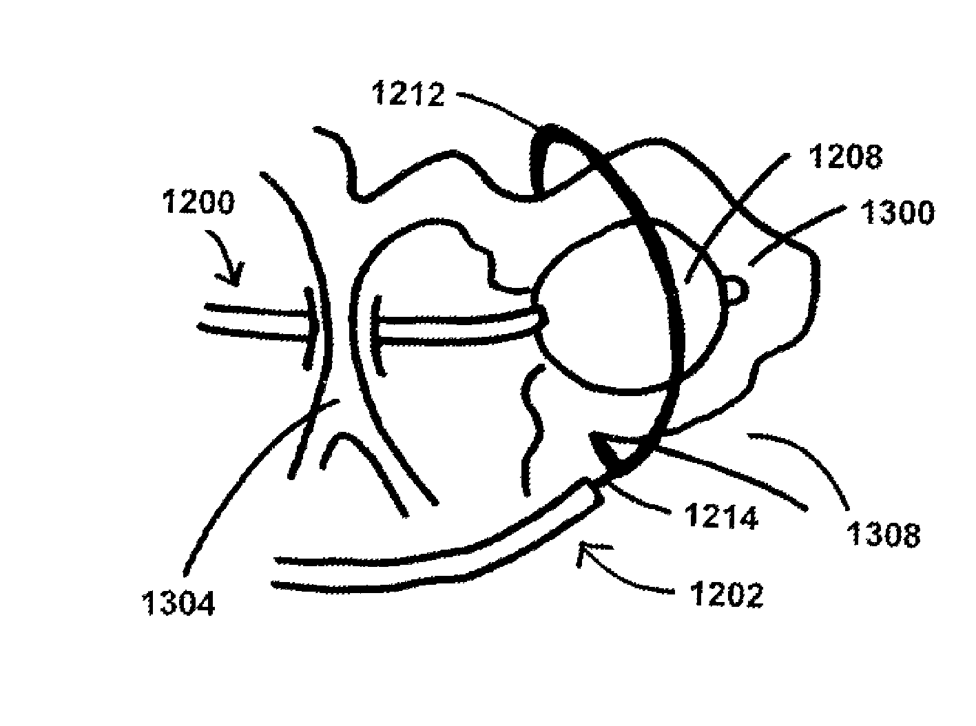
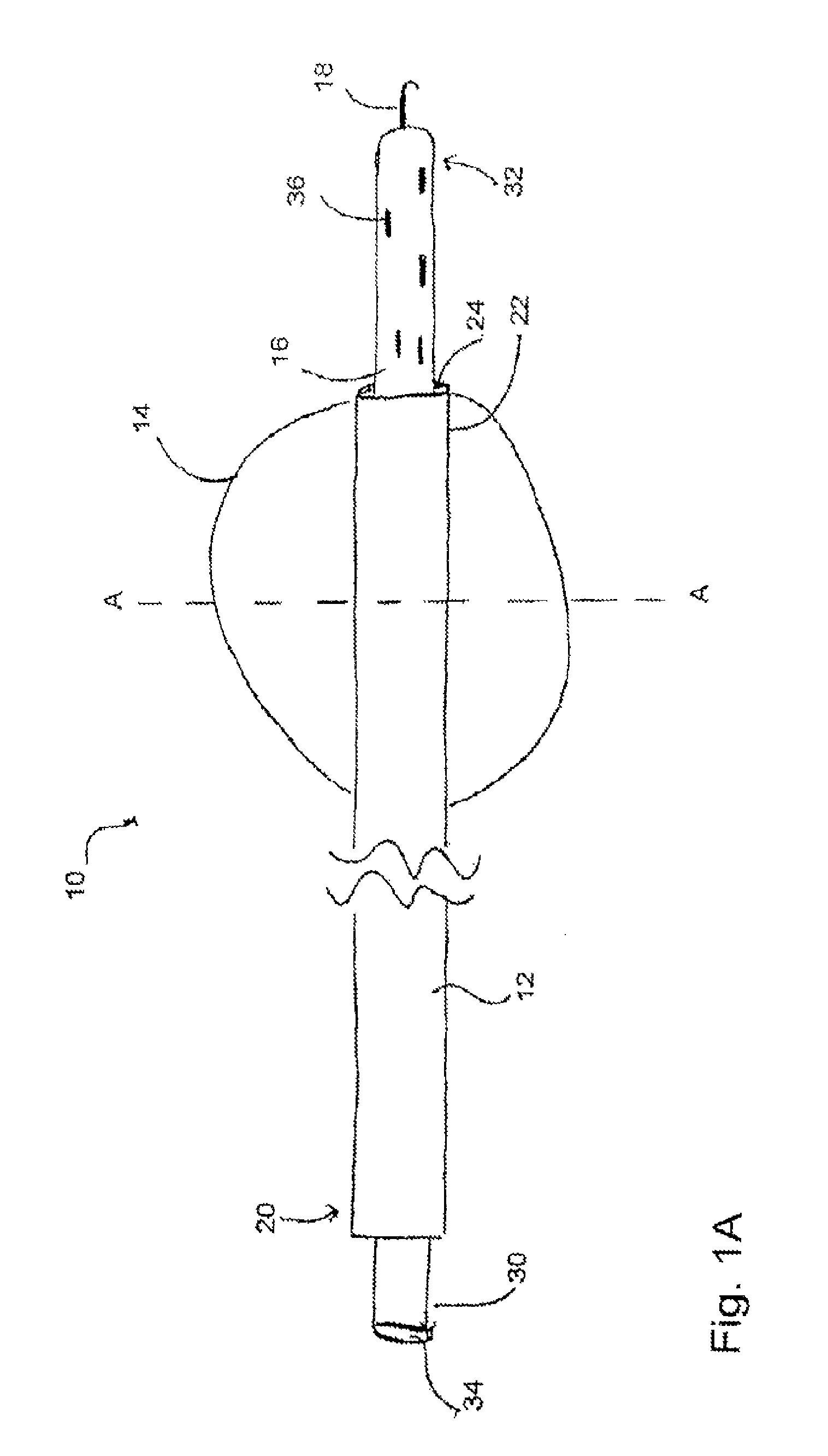
[0044]FIG. 1A shows a side view of one embodiment of an occlusion assembly 10 for closing a left atrial appendage. Specifically, the assembly 10 is configured for placement within the left atrial appendage (“LAA”) and is delivered non-surgically through the use of catheterization and percutaneous transluminal access.

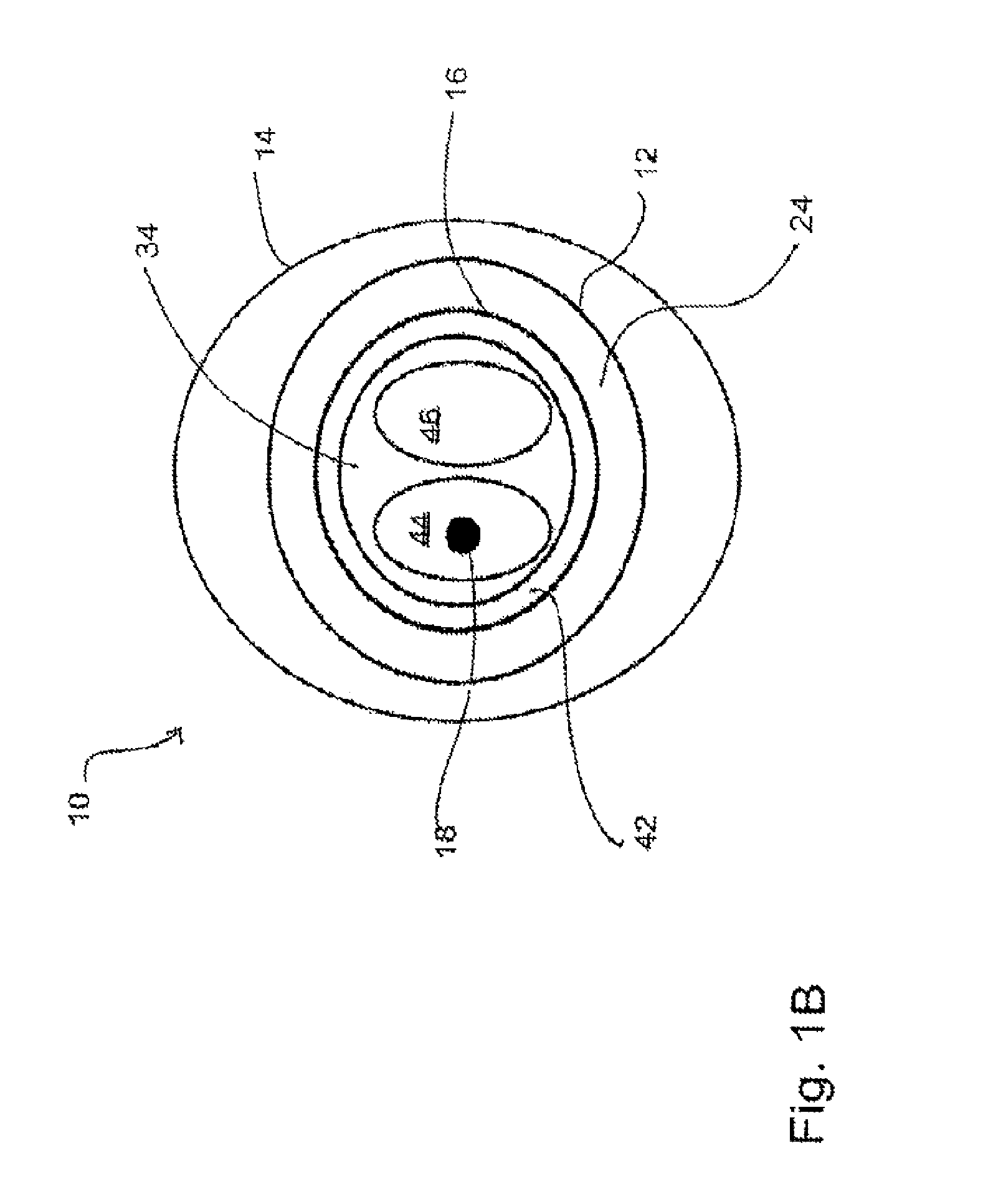
[0045]The occlusion assembly 10 comprises a shaft 12, a balloon 14, a catheter 16, and a guidewire 18. The shaft 12 comprises an elongated catheter shaft having a proximal end 20, a distal end 22, and an interior 24. Both the proximal end 20 and the distal end 22 of the shaft 12 are open and in communication with the interior 24. The interior 24 of the shaft 12 extends throughout the length of the shaft 12 and provides a ch...


PUM


Abstract

Methods for occluding an atrial appendage. The steps of an exemplary method include introducing at least a portion of the first device in a heart, introducing at least a portion of a second device into a pericardial space surrounding the heart, positioning the balloon of the first device at least partially within an atrial appendage cavity, inflating the balloon to displace blood present within the atrial appendage cavity, positioning the loop of the second device around the atrial appendage, tightening the loop around the atrial appendage, deflating the balloon to allow for ultimate removal of the first device from the atrial appendage cavity, and separating the loop from the second device so that the loop remains positioned and tightened around the atrial appendage.

Description

PRIORITY[0001]The present application is related to, and claims the priority benefit of, International Patent Application Serial No. PCT / US2009 / 030222, filed Jan. 6, 2009, which is related to, is a continuation-in-part application of, and claims the priority benefit of, International Patent Application Serial No. PCT / US2008 / 000838, filed Jan. 23, 2008, which is related to, and claims the priority benefit of, U.S. Provisional Patent Application Ser. No. 60 / 881,831, filed Jan. 23, 2007. The contents of each of these applications are hereby incorporated by reference in their entirety into this disclosure.BACKGROUND[0002]Currently, 2.2 million patients in the United States suffer atrial fibrillation (“AF”). About half of these patients are considered to be at a high risk for stroke. The Stroke Prevention in Atrial Fibrillation trials (SPAF, SPAF II, SPAF III) have shown that chronic warfarin therapy reduces the risk of stroke by about 70%. Nevertheless, problems related with the long te...

Claims


Application Information

Patent Timeline
Patent Type & Authority Patents(United States)
IPC IPC(8): A61D1/00
CPCA61B17/00491A61B17/0057A61B17/12013A61B17/12022A61B17/12122A61B17/12181A61B17/12186A61B17/1227A61B17/1285A61M25/10A61B2017/00243A61B2017/00632A61B2017/0065A61B2017/00867A61B2017/22067A61B2017/306A61M25/007A61M2025/0086A61M2025/1052A61B17/122A61B2017/00557A61B2017/00876A61B2017/22038A61B2217/005A61M25/0084A61M2025/0085A61M25/0032A61M25/0041A61M25/0102A61M25/1002A61M2025/0096A61M2025/0681
Inventor KASSAB, GHASSAN S.NAVIA, SR., JOSE A.
Owner CVDEVICES
Why Eureka
Try Eureka