
Sliding pendulum seismic isolation system

a technology of seismic isolation system and sliding pendulum, which is applied in the direction of shock-proofing, machine supports, other domestic objects, etc., can solve the problems of increasing the effective friction of the isolation system, increasing the displacement amplitude of the supported structure, and the bearing configuration is not cost-effective to support light loads, so as to reduce the cost of the isolation bearing, the seismic gap, and the supported structure.

Active Publication Date: 2013-07-16
EARTHQUAKE PROTECTION SYST
View PDF18 Cites 17 Cited by
  • Summary
  • Abstract
  • Description
  • Claims
  • Application Information

AI Technical Summary

Benefits of technology

This patent is about a method for configuring a seismic isolation system for buildings and other structures. The method involves using sliding pendulum bearings that can adjust their effective length based on the strength of seismic motions. The bearings are organized in series, with different pendulum mechanisms becoming active at different strengths of motion. The systems can accommodate different types and sizes of loads at different points of support. The use of specific bearing configurations can significantly reduce the cost of the structural frame. Overall, the method reduces the seismic forces transmitted to the structure, reduces the displacement of the bearings, and reduces the cost of the isolation system. Various bearing configurations are presented to achieve these results, and they can be tailored to different needs and loads.

Problems solved by technology

Another primary concept of the method is to configure the isolation system in such a manner as to cause substantial increases in the effective friction of the isolation system when increases in the strength of the earthquake motions cause increases in the displacement amplitudes of the supported structure.
However, these bearing configurations are not cost-effective to support light loads, and accommodate large seismic displacements.

Method used


Image

  • Sliding pendulum seismic isolation system
  • Sliding pendulum seismic isolation system
  • Sliding pendulum seismic isolation system

Examples


Embodiment Construction

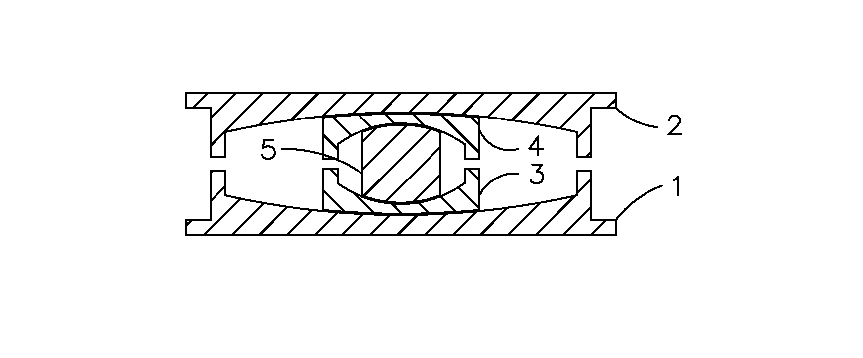
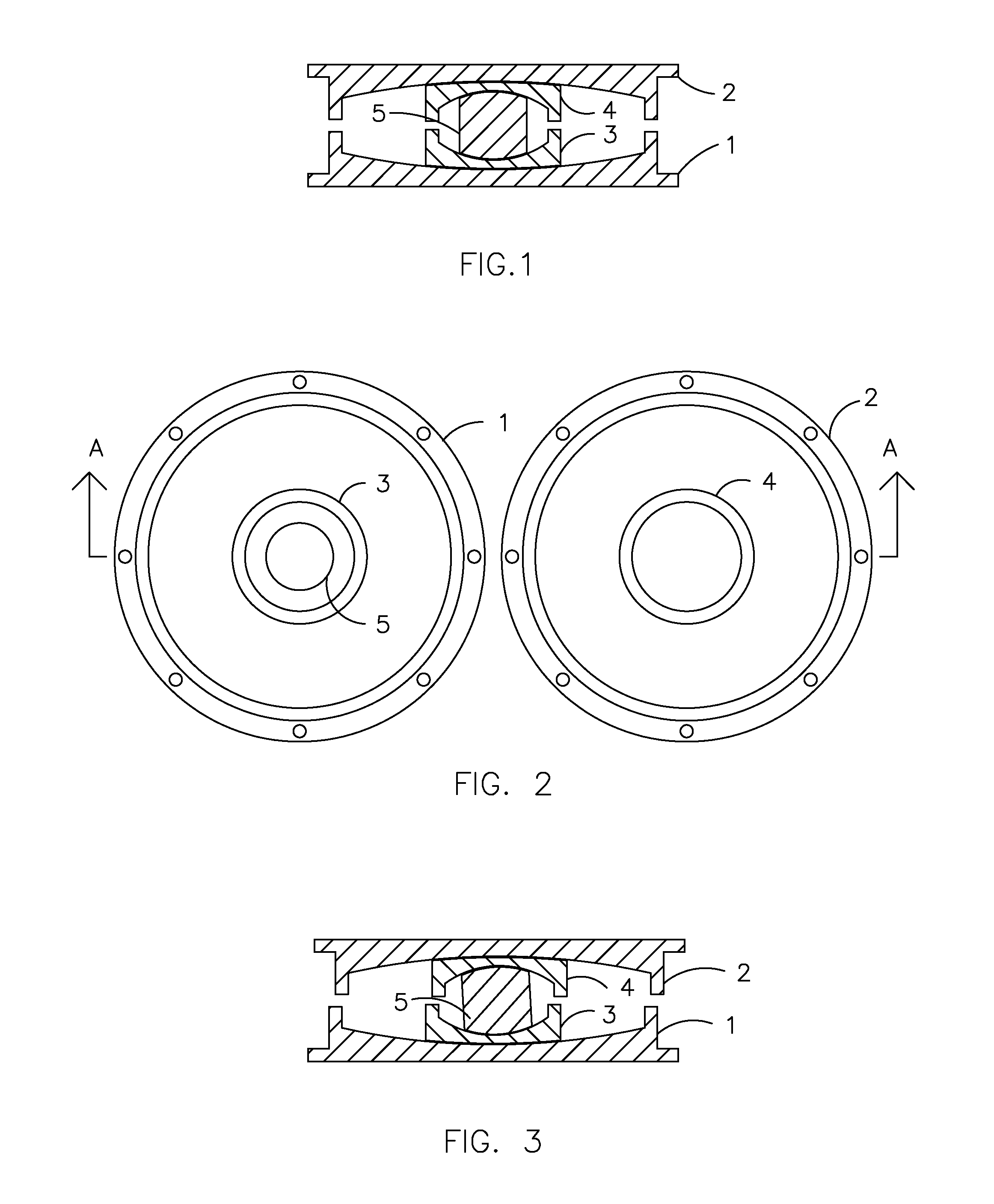
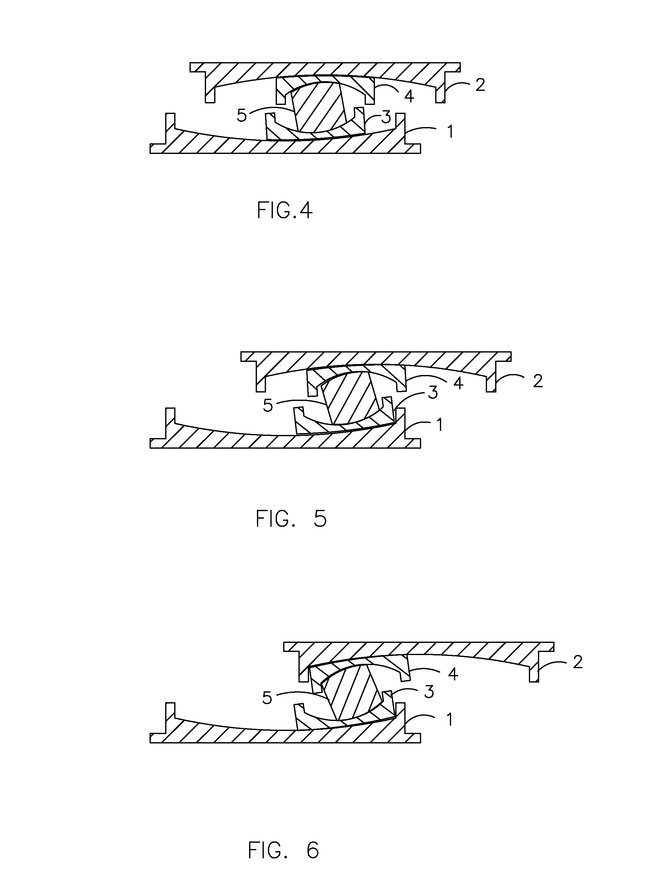
[0037]In past applications of the prior-art sliding pendulum bearings to buildings, the authors have used between 12 to 267 seismic isolation bearings distributed throughout the structure at each support point. To implement the inventive method presented herein, different bearing configurations are required for different support conditions, depending on the type and magnitude of load to be supported, and the displacement capacity required. In combination, the multiple bearing supports implement a seismic isolation system following the inventive method prescribed herein. Six different bearing configurations for sliding pendulum bearings are presented to accommodate the varied conditions encountered in the applications of such a system to buildings, bridges and industrial facilities. No one bearing configuration presented herein is capable of meeting the objectives of the inventive method for the varied different support conditions encountered, for the various types of structures to b...


PUM


Abstract

An inventive method is presented for a sliding pendulum seismic isolation system that reduces seismic forces on the supported structure and reduces the costs of the isolation bearings, seismic gaps, and supported structural frame. The inventive method is to configure the isolation system to achieve increased effective friction with increased displacement amplitudes, and to employ specific bearing configurations that suit the different types and magnitudes of loads present at particular structure support locations. Three bearing configurations are presented which are comprised of multiple sliders that slide along different concave spherical surfaces, each constituting an independent sliding pendulum mechanism having a specified pendulum length and friction. Two bearing configurations are presented which are comprised of multiple sliders that slide along different concave or convex cylindrical surfaces, one configured to carry both compression and tension loads, and one configured to be cost-effective for carrying light compression loads and accommodating large displacements.

Description

CROSS-REFERENCE TO RELATED APPLICATIONS[0001]Not applicable.STATEMENT REGARDING FEDERALLY SPONSERED RESEARCH AND DEVELOPMENT[0002]Not applicable.REFERENCE TO SEQUENCE LISTING, A TABLE, OR A COMPUTER PROGRAM LISTING COMPACT DISC APPENDIX[0003]Not applicable.BACKGROUND OF THE INVENTION[0004]Improvements are presented to the prior-art in the field of sliding pendulum seismic isolation systems.[0005]The prior-art sliding pendulum bearings employ concave spherical or cylindrical surfaces, and sliders, which slide along these concave surfaces, resulting in a lifting of the supported structure during seismic ground motions. The lifting of the structure results in an equivalent pendulum motion. The radii of curvature of the concave surfaces result in an effective length of the pendulum arm, that determines the dynamic natural period of vibration of the isolation system. The friction, which occurs between the sliders and the concave surfaces, serves the important function of dissipating the ...

Claims


Application Information

Patent Timeline
Patent Type & Authority Patents(United States)
IPC IPC(8): E04B1/98E04H9/02
CPCE04H9/023E04H9/021
Inventor ZAYAS, VICTORLOW, STANLEY
Owner EARTHQUAKE PROTECTION SYST
Learn More