Clutch mechanism with overload protection

a technology of overload protection and clutch mechanism, which is applied in the direction of interengaging clutches, slip couplings, and gearing, etc., can solve the problems of inconvenient operation, inability to maintain, and the control box is adverse to the compact layout of the automated machine, so as to achieve constant friction between the magnets, save power, and be more stable and durable.

Inactive Publication Date: 2013-07-16
HIWIN MIKROSYST
View PDF4 Cites 5 Cited by
  • Summary
  • Abstract
  • Description
  • Claims
  • Application Information

AI Technical Summary

Benefits of technology

[0008]One objective of the present invention is to provide the clutch mechanism wherein the overload protection is realized by coupling and disconnecting the power input shaft to and from the power output shaft mechanically without using any external power source and control box. Thus, the clutch mechanism has no problem related to worn coils and is more stable and durable while favoring a compact layout of an automated machine using it.
[0009]Another objective of the present invention is to provide the clutch mechanism wherein the magnetic attraction of the magnet set makes the clutch mechanism normally establish the power transmission between the motor and the power output shaft, and helps to recover the power transmission after overload protection.
[0010]Another objective of the present invention is to provide the clutch mechanism wherein the desired overload protection between the power input shaft and the power output shaft can be customized by designing the friction assembly with different thickness that in turn affect the magnetic attraction of the magnet set, so as to meet various practical needs.
[0011]Still another objective of the present invention is to provide the clutch mechanism wherein there is need for any external power source, thus saving power.
[0012]Yet another objective of the present invention is to provide the clutch mechanism wherein the magnet set and the friction assembly may be arranged in the retarding mechanism of the actuator, so that by manual operation, engagement and disengagement between the power input shaft and the power output shaft can be rapidly achieved.

Problems solved by technology

Summarily, the existing electromagnetic clutch for linear actuators has the shortcomings including that its indirect overload protection can only work when there is power supplied, that it is not durable because the coils tend to get worn after long-term use, and that the control box is adverse to a compact layout of the automated machine.

Method used


Image

  • Clutch mechanism with overload protection
  • Clutch mechanism with overload protection
  • Clutch mechanism with overload protection

Examples


Embodiment Construction

[0020]Particular preferred embodiments will be described in order to illustrate the concepts of the present invention as provided in SUMMARY OF THE INVENTION. The accompanying drawings are not made to scale but with the proportions, dimensions, deformation and / or displacement favorable to the illustrative purpose. In different drawings, the same numeral is used to indicate the similar components.

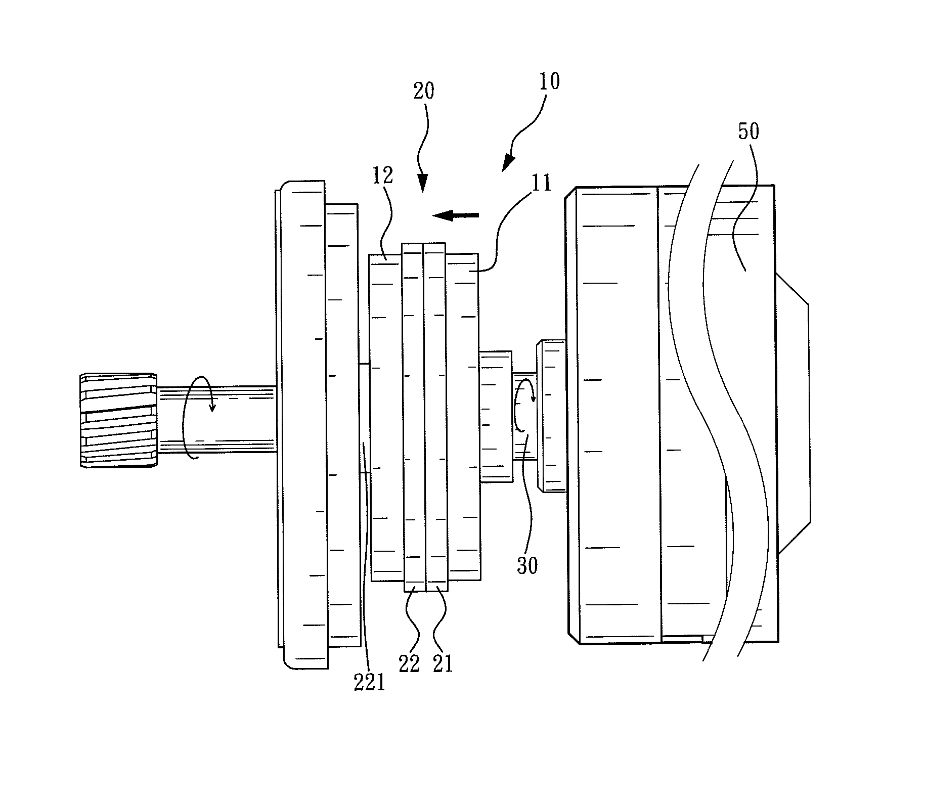
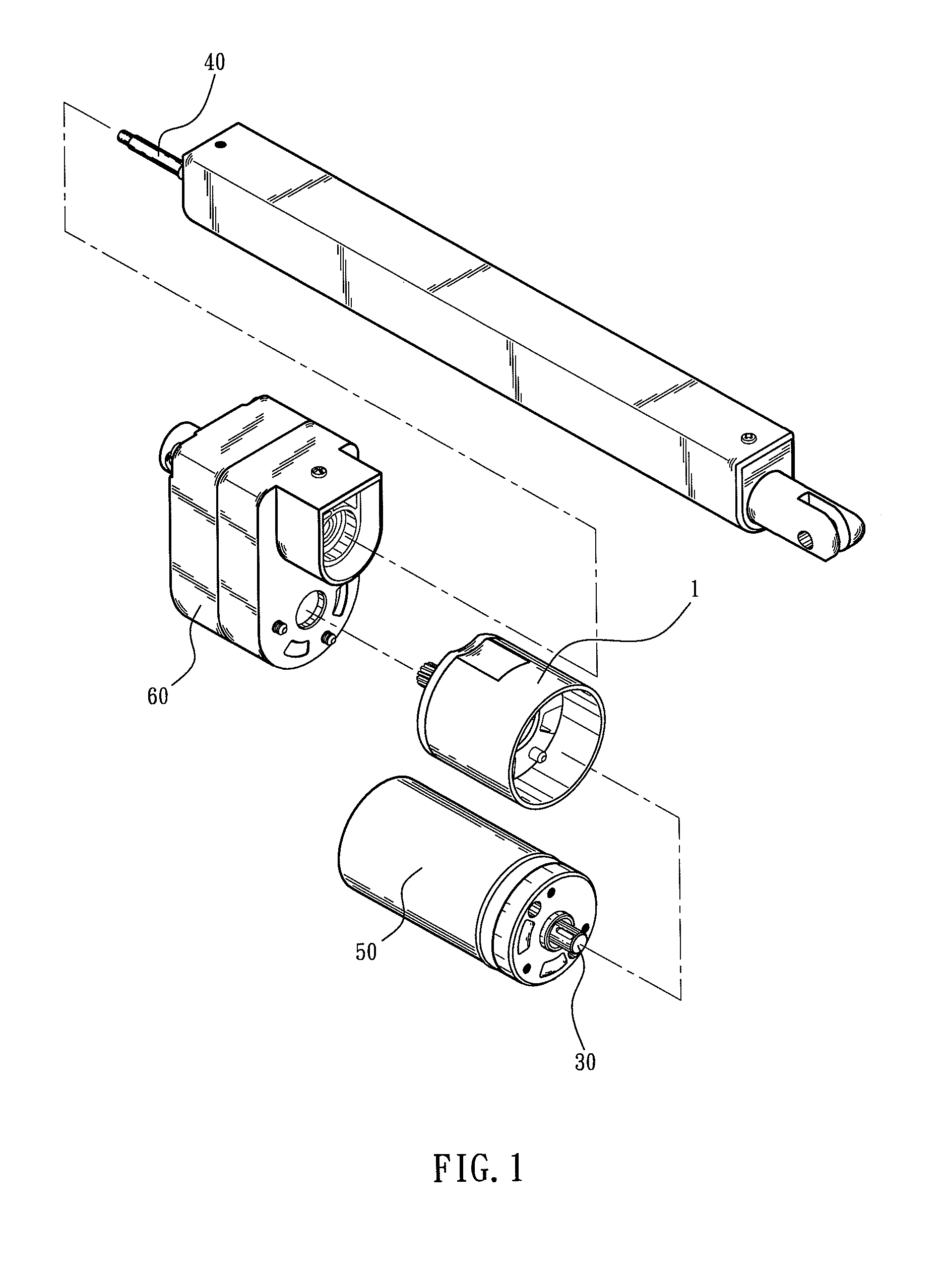
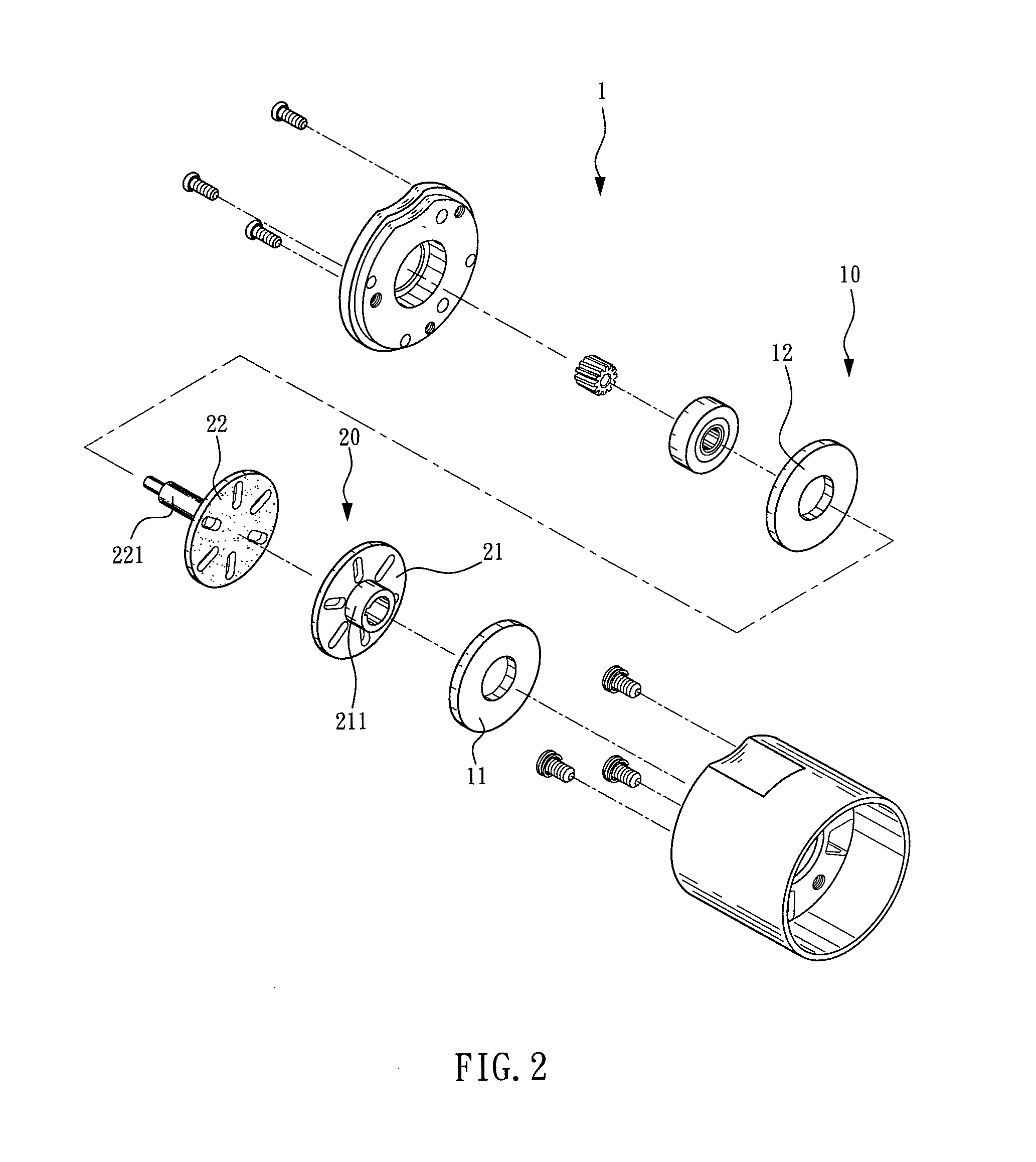
[0021]Referring to FIG. 1 and FIG. 2, the present invention provides a clutch mechanism 1 with overload protection. The clutch mechanism 1 primarily comprises a magnet set 10 and a friction assembly 20. The clutch mechanism 1 is deposited between a power input shaft 30 and a power output shaft 40 of an actuator. Therein, the power input shaft 30 is driven by a motor 50, and the power output shaft 40 is a screw, while the clutch mechanism 1 controls the power input shaft 30 and the power output shaft 40 to couple with or disconnect from each other.

[0022]The magnet set 10 has at least a first ...


PUM


Abstract

A clutch mechanism with overload protection provided between a power input shaft and a power output shaft of an actuator includes a magnet set including at least a first magnet and a second magnet that are arranged as magnetically attractive to each other and are attached to the power input shaft and the power output shaft, respectively; and a friction assembly including a first friction member and a second friction member arranged adjacent to each other and between the first magnet and the second magnet, so as to provide a constant friction between the magnets. The magnet set and the friction assembly jointly set a limit of a torque between the power input shaft and the power output shaft. When the torque exceeds the limit, the power input shaft and the power output shaft are disconnected, so as to achieve overload protection.

Description

BACKGROUND OF THE INVENTION[0001]1. Technical Field[0002]The present invention relates to clutch mechanisms, and more particularly, to a clutch mechanism with overload protection, which is applicable to motor-driven devices requiring overload protection, such as actuators.[0003]2. Description of Related Art[0004]With the progress of automation, linear actuators have become a vital component in automated machines and are extensively used in electric beds, lift chairs, electric tables, lift platforms, power windows and so on. A linear actuator is conventionally composed of a housing, a motor, a transmission mechanism and a push rod. The motor transfers a rotational motive force to the push rod through the transmission mechanism. The push rod comprises a screw and an extension tube. The screw has a screw shaft and a nut, wherein the nut converts the rotational motive force from the screw shaft into a linear thrust that drives the extension tube attached to the nut so that the extension...

Claims


Application Information

Patent Timeline
Patent Type & Authority Patents(United States)
IPC IPC(8): F16D7/02F16D27/01
CPCF16D7/025F16D27/01Y10T464/30F16H25/2021H02K49/104
Inventor CHIANG, HSIN-ANHU, CHING-FANG
Owner HIWIN MIKROSYST
Why Eureka
Try Eureka