Process and apparatus for filtration and pre-distribution of gas and liquid phases in a down-flow catalytic reactor

a technology of down-flow catalytic reactor and process and apparatus, which is applied in the direction of filter cartridges, separation processes, filtration separation, etc., can solve the problem of not being able to control the ratio between the deflected liquid and the gas stream in the tube comprising the system, and achieve the effect of contributing to good gas distribution

Active Publication Date: 2013-07-16
INST FR DU PETROLE
View PDF13 Cites 18 Cited by
  • Summary
  • Abstract
  • Description
  • Claims
  • Application Information

AI Technical Summary

Problems solved by technology

The device described in the cited patents cannot control the ratio between the deflected liquid and gas streams in the tubes comprising said system.

Method used


Image

  • Process and apparatus for filtration and pre-distribution of gas and liquid phases in a down-flow catalytic reactor
  • Process and apparatus for filtration and pre-distribution of gas and liquid phases in a down-flow catalytic reactor
  • Process and apparatus for filtration and pre-distribution of gas and liquid phases in a down-flow catalytic reactor

Examples


example

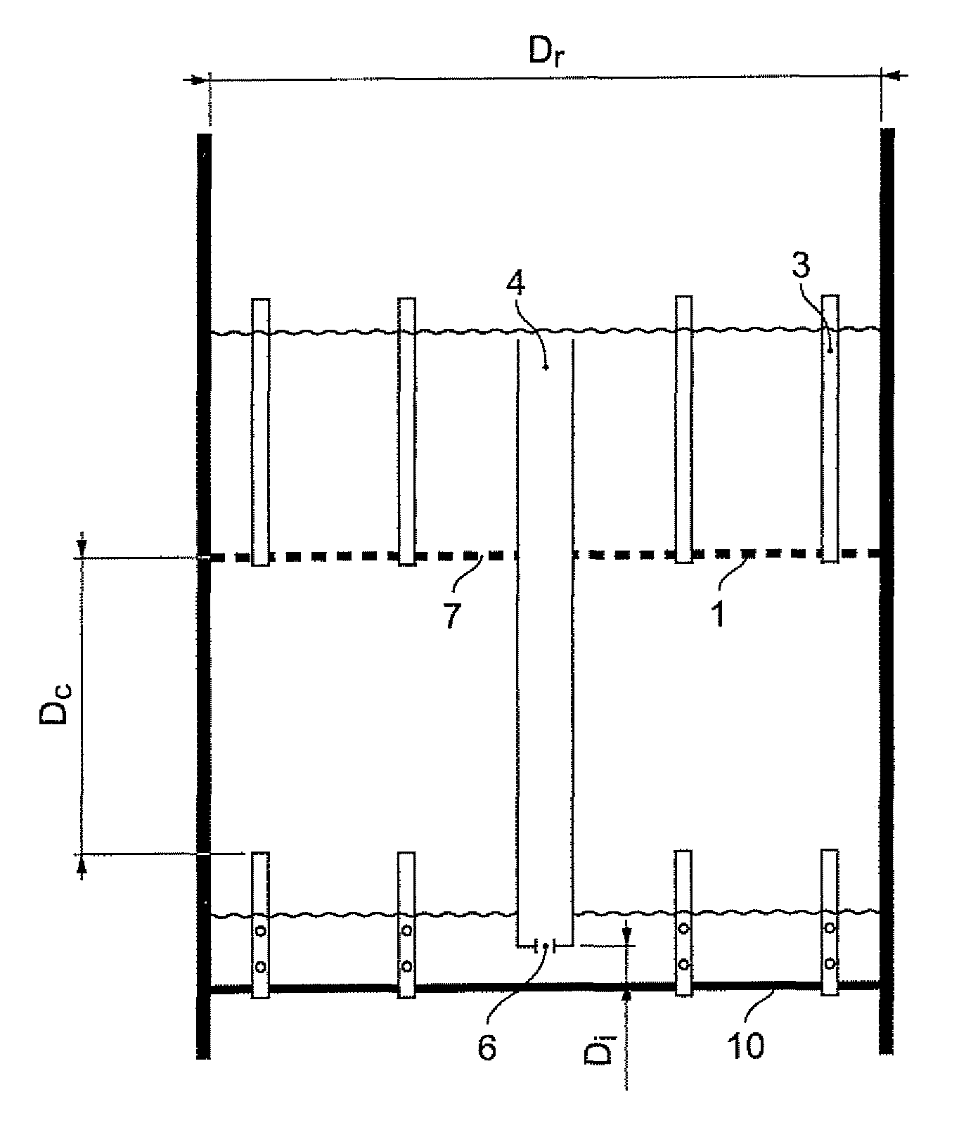
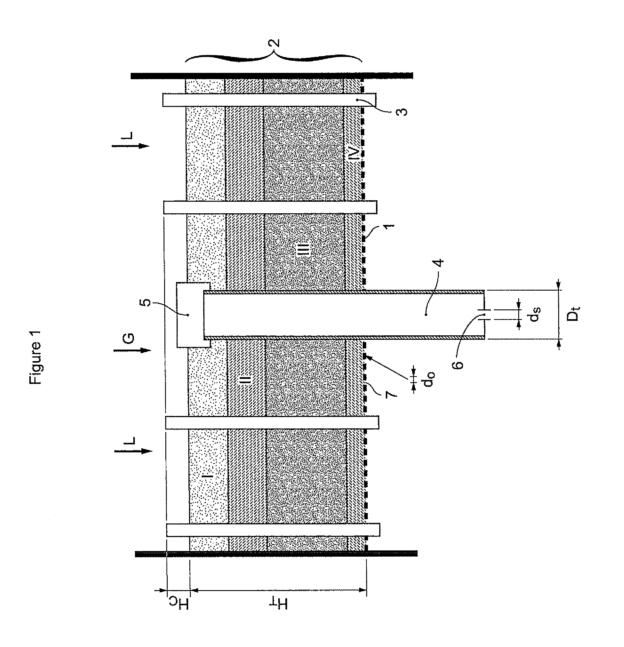
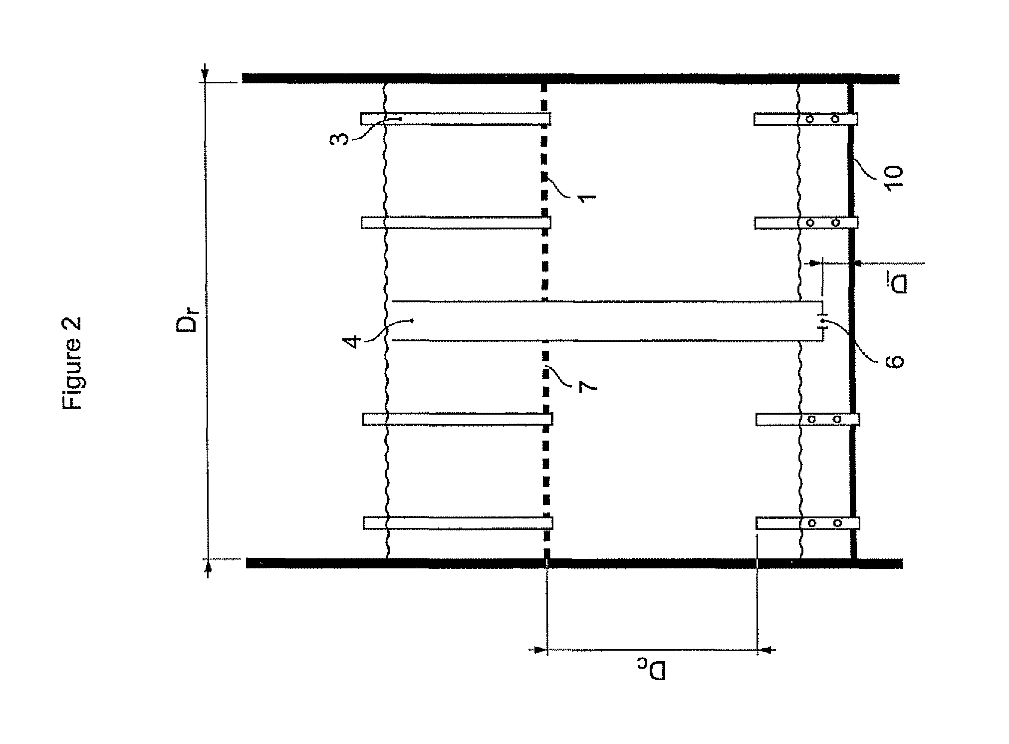
[0089]The following example is a comparative example between two configurations of a selective hydrogenation reactor:[0090]a configuration A with a single distributor plate;[0091]a configuration B with the distributor plate of configuration A preceded by the pre-distribution plate with an overflow tube in accordance with the present invention.

[0092]The reactor had a diameter of 1 metre and a total height of 5 metres including the pre-distribution plate of the invention, the downstream distributor plate and the catalytic bed.

[0093]The catalytic bed was composed of particles of a traditional catalyst for carrying out selective hydrogenation. It was a catalyst containing Ni deposited on an alumina support.

[0094]The size of the catalyst particles forming the catalytic bed located downstream of the downstream distributor plate was 2 mm.

[0095]The supply to the reactor was composed of a liquid portion and a gas portion.

[0096]The liquid was constituted by a pyrolysis gasoline with a distill...


PUM

PropertyMeasurementUnit
diameteraaaaaaaaaa
diameteraaaaaaaaaa
diameteraaaaaaaaaa

Abstract

The device described in the present invention allows pre-distribution of the gas and liquid feed supplying a reactor functioning in gas and liquid co-current downflow mode to be carried out by means of a pre-distribution plate comprising a filtration medium and an overflow tube in order to regulate the flow of liquid arriving on the distributor plate located downstream of said device.More particularly, the present invention is applicable to the selective hydrogenation treatment of feeds containing acetylenic and dienic compounds.

Description

FIELD OF THE INVENTION[0001]The invention relates to the field of distributor plates intended to supply chemical reactors operating in gas and liquid co-current downflow mode with gas and liquid.[0002]Such reactors are encountered in the refining field, more particularly in reactions for the selective hydrogenation of various oil cuts, and more generally in hydrotreatments which require streams of hydrogen under high pressure and operate with heavy liquid feeds which may contain impurities constituted by solid plugging particles.[0003]In some cases, the liquid feed contains impurities which may be deposited on the catalytic bed itself and, over time, reduce the interstitial volume of that catalytic bed.[0004]Plugging liquid feeds which may be cited include mixtures of hydrocarbons containing 3 to 50 carbon atoms, preferably 5 to 30 carbon atoms, and possibly containing a non-negligible proportion of unsaturated or poly-unsaturated compounds acetylenic or dienic compounds, or a combi...

Claims


Application Information

Patent Timeline
Patent Type & Authority Patents(United States)
IPC IPC(8): C07C7/163
CPCB01J8/0278B01J8/0453C10G49/00C10G31/09B01J8/0492B01J2208/00707B01D24/22B01J8/02B01J8/04
Inventor KOUDIL, ABDELHAKIMBOYER, CHRISTOPHE
Owner INST FR DU PETROLE
Why Eureka
Try Eureka