Injector sleeve removal tool

a technology of injector sleeves and sleeve covers, which is applied in the direction of metal-working equipment, metal-working equipment, manufacturing tools, etc., can solve the problems of leakage, cost in time and money, etc., and achieve the effect of increasing safety, stable and powerful

Active Publication Date: 2013-07-23
WHITAKER TOOLS
View PDF19 Cites 5 Cited by
  • Summary
  • Abstract
  • Description
  • Claims
  • Application Information

AI Technical Summary

Benefits of technology

[0007]A tool is disclosed herein used for removing an injector sleeve from the cylinder head of a diesel engine without the extra labor and cost of removing the entire head from the diesel engine.
[0008]An injector sleeve is used to seal each of the cavities in the top of a cylinder head or heads of a diesel. The sleeve maintains a clean environment within the cylinder head cavity by keeping external debris outside. The sleeve is generally made of brass or bronze and is sized to be pressed into the cavity. If the sleeve fails, leaks can occur and it must be replaced. This can require removal of the cylinder head, which is costly in terms of time and money. A huge savings is realized if the sleeve or sleeves can be removed without the removal of the cylinder head. The present invention is a tool which makes sleeve removal possible without removing the cylinder head.
[0012]Experience has shown that two or three turns of thread into the sleeve are sufficient to pull the sleeve. One superior aspect of this design is that one can turn in more threads if required. Also, the pulling method is the even, central and straight thrust provided when the loose nut is tightened against the flat washer bearing surface member. This is believed to be more stable and powerful than that of tools that use the uneven strikes of a slide hammer.
[0013]A major feature of the present invention is that it allows the sleeves to be removed without having to remove the engine from the vehicle saving time, labor, expense, and increasing safety.

Problems solved by technology

If the sleeve fails, leaks can occur and it must be replaced.
This can require removal of the cylinder head, which is costly in terms of time and money.

Method used


Image

  • Injector sleeve removal tool
  • Injector sleeve removal tool
  • Injector sleeve removal tool

Examples


Embodiment Construction

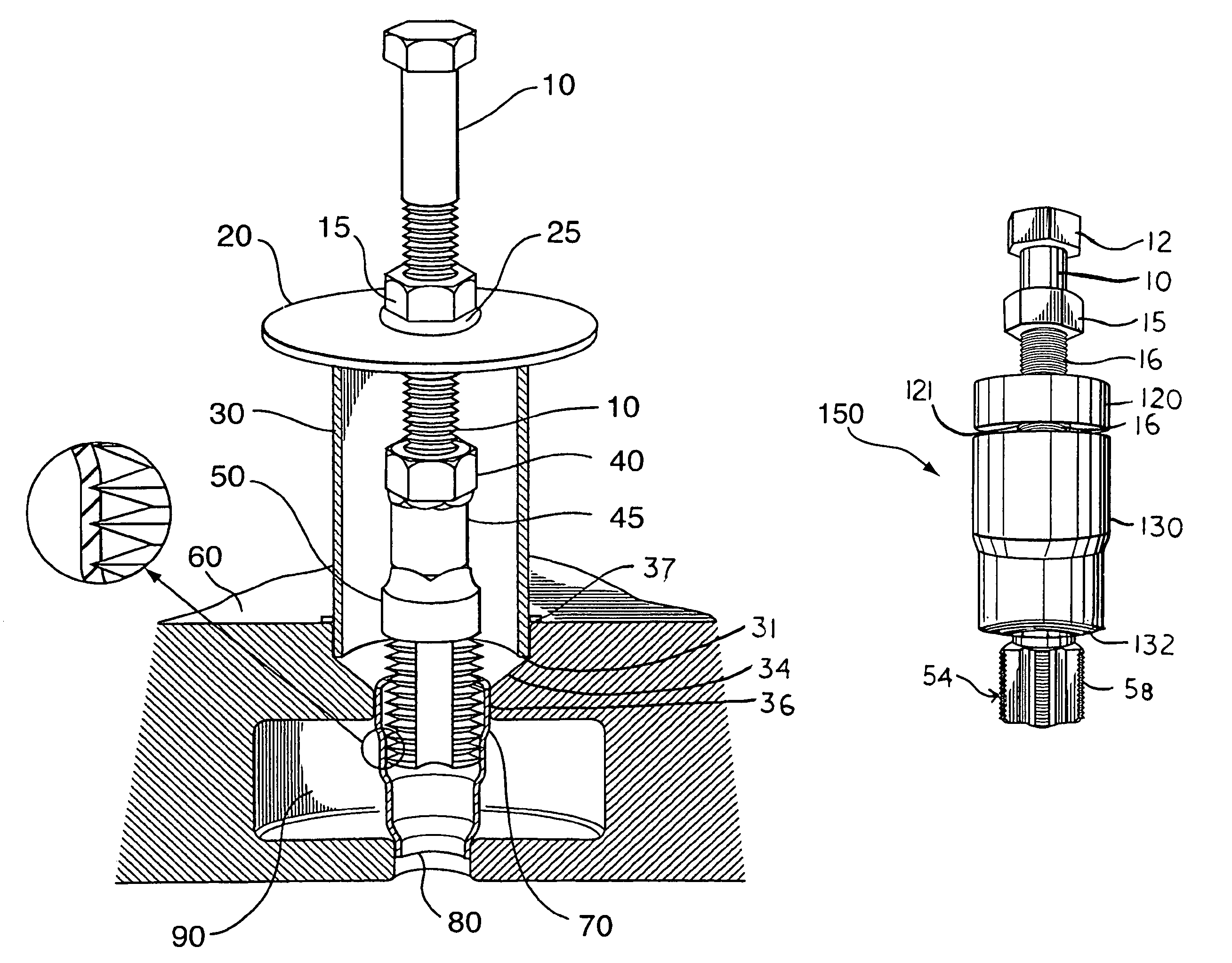
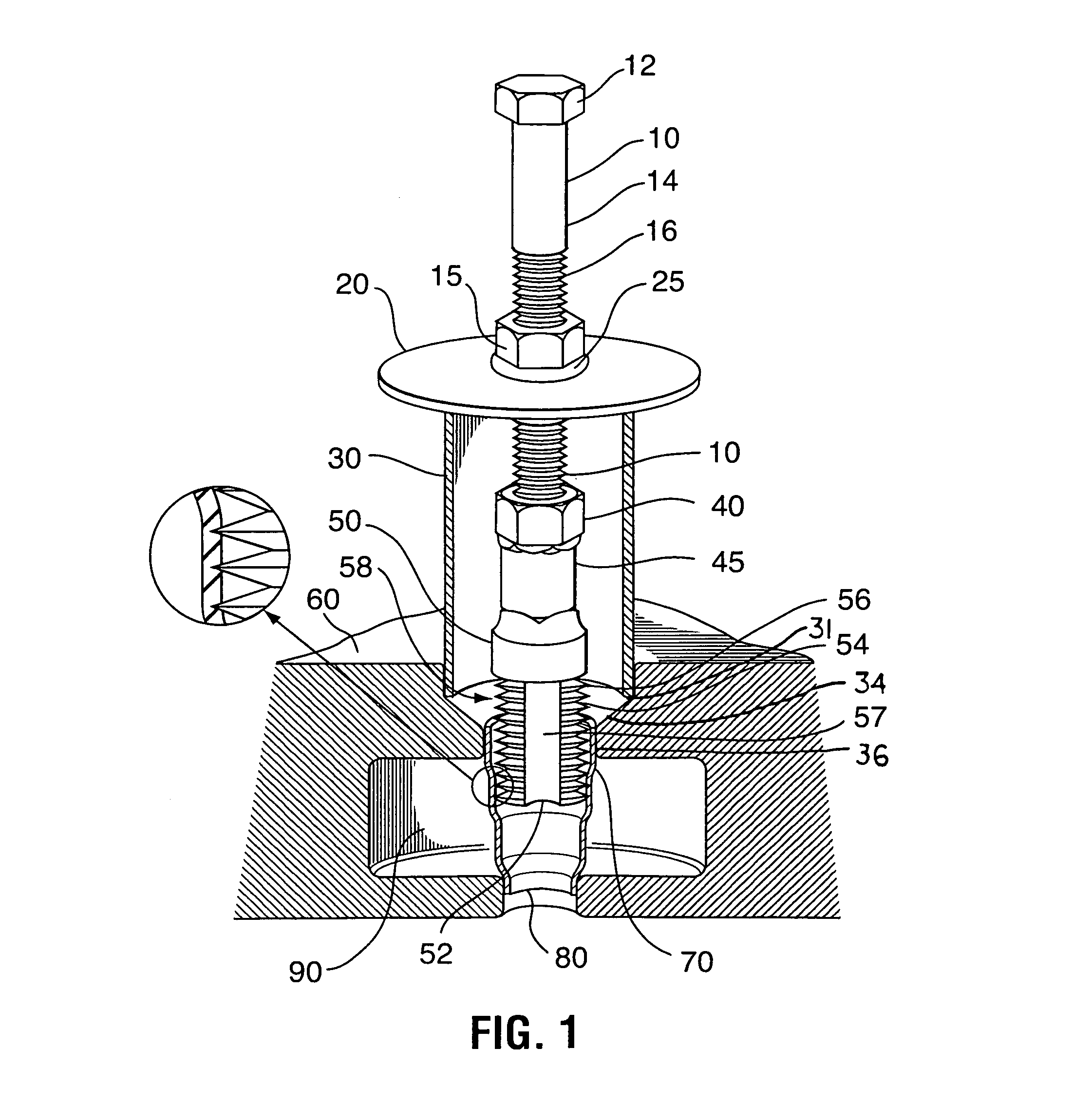
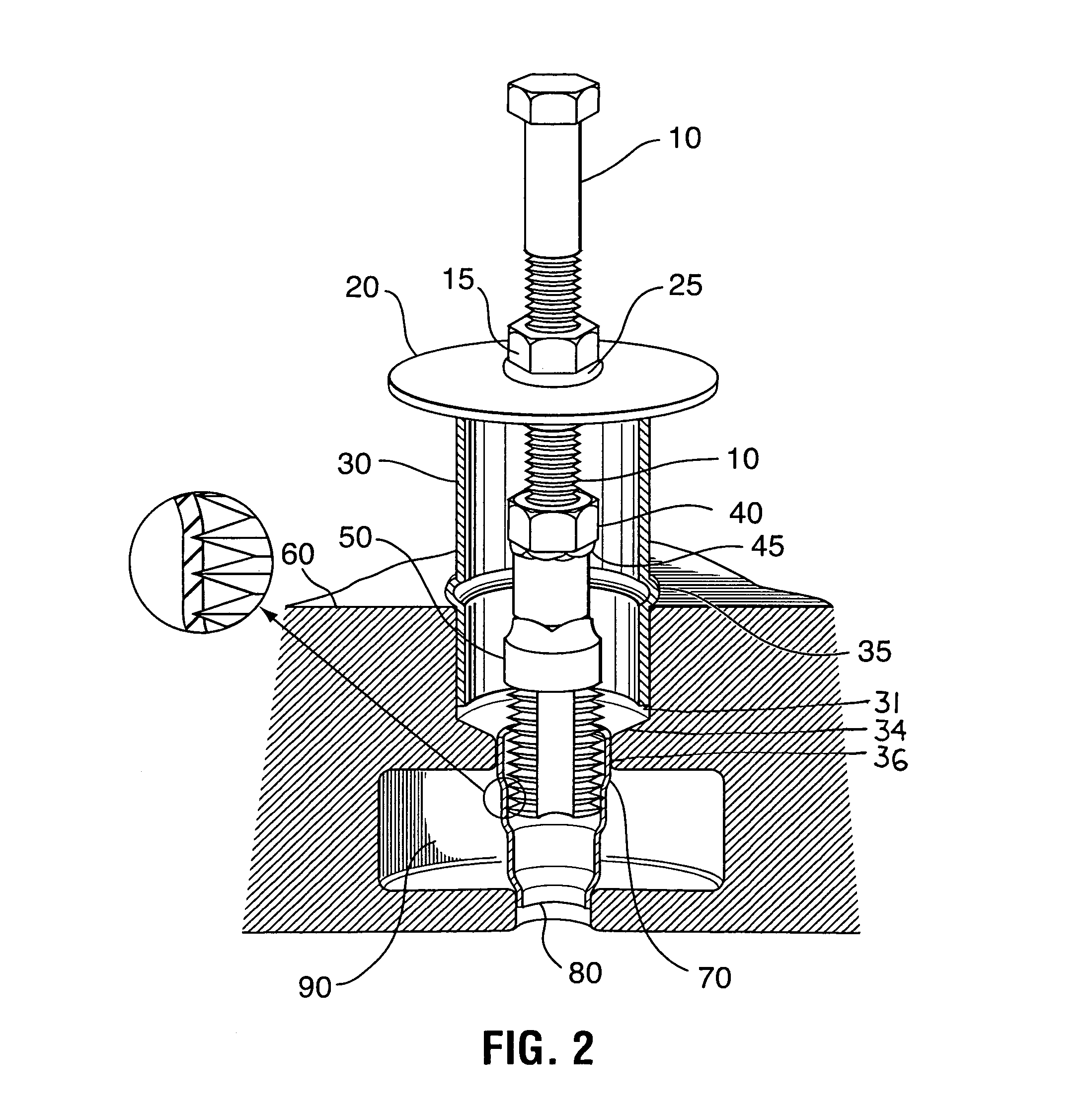
[0028]In accordance with the present invention, a tool is disclosed herein used for removing an injector sleeve from the cylinder head of a diesel engine without the extra labor and cost of removing the entire head from the diesel engine.

[0029]FIGS. 1-4 show the assembled tool for removing an injector sleeve described as follows. An axially moveable threaded rotating extraction nut 15 is threaded onto a drive member 7 including a bolt 10 having a head 12 defining a holding means extending from a shaft 14 having threads 16 at least along its distal end opposite the head 12. In the embodiment of FIG. 1, about one and one half inches of the threads 16 of bolt 10 extend through rotating nut 15.

[0030]A tap 50 threadably engages the bolt 10. As shown in FIG. 1-4, the tap 50 includes a means for holding a threaded member having an external holding means comprising stationary nut 40 is attached by means such as welding or casting onto a non-threaded distal end 45 of the tap 50. The opposing...


PUM

PropertyMeasurementUnit
inner diameteraaaaaaaaaa
outer diameteraaaaaaaaaa
lengthaaaaaaaaaa

Abstract

A tool for removing an injector sleeve from the cylinder head of a diesel engine between the rocker arms while the head remains mounted to the engine block within the vehicle. The devices includes a tap having a longitudinal body and a thread cutting head at one end. A drive member comprises a bolt having a head at one distal end. An extraction nut is threaded onto the threaded shaft of the drive member followed by a bearing surface member such as a spacer. A hollow cylinder or support sleeve having an internal diameter greater than the injector sleeve to be removed and an external diameter less than the diameter of the sleeve bore includes a shoulder member.

Description

RELATED APPLICATIONS[0001]This application claims priority from U.S. Provisional Patent application Ser. No. 61 / 190,441 filed on Aug. 28, 2008 which is incorporated by reference herein in its entirety.BACKGROUND OF THE INVENTION[0002]1. Technical Field[0003]The present invention relates to the field tools used to remove a typically brass or bronze injector sleeve from a cylinder head in a diesel engine. These sleeves are press fit into a bore in the head. After years of use the sleeves will loosen or begin to leak and need to be replaced.[0004]2. Description of the Related Art[0005]Tools for the removal of injector sleeves have been described and patented in recent years. U.S. Pat. No. 5,784,783 by Carpenter for METHOD OF REMOVING AND INJECTOR SLEEVE issued on Jul. 28, 1998 claims a tool wherein one inserts rounded head into the sleeve. A cylinder with a reverse tapered edge is forced down onto the top edge of the sleeve. This flairs the top edge inward, thus capturing the rounded h...

Claims


Application Information

Patent Timeline
Patent Type & Authority Patents(United States)
IPC IPC(8): B23P19/04
CPCB25B27/023B25B27/062Y10T29/53943Y10T29/53883Y10T29/53909
Inventor WHITAKER, TONY
Owner WHITAKER TOOLS
Why Eureka
Try Eureka