Flash and sound suppressor for a firearm

a suppressor and firearm technology, applied in the field of flash and sound suppressors for firearms, can solve the problems of more difficult to detect the location of the marksman, difficult to locate the marksman, etc., and achieve the effect of convenient operation of the suppressor, quick installation and fast cooling

Active Publication Date: 2013-07-23
FN AMERICA +1
View PDF17 Cites 61 Cited by
  • Summary
  • Abstract
  • Description
  • Claims
  • Application Information

AI Technical Summary

Benefits of technology

[0005]The present invention is a combination of a flash hider, a sound suppressor and a coupler that holds the sound suppressor to a flash hider. The flash hider does not need to be removed to use the sound suppressor or replaced after the sound suppressor is removed. Furthermore, the coupler enables the suppressor to be attached to the flash hider rather than to the barrel proximate to the flash hider so that the flash hider forms a nozzle at the entrance to the sound suppressor and thereby facilitates the operation of the suppressor. The present coupler also enables the sound suppressor to be removed and installed quickly and securely.
[0006]A feature of the present flash hider is that it is characterized by three tines that are slightly tapered, that are long, and that contain stepped features on their sides that face the gaps between the tines. These stepped features expand the distance between the tines for hot gases traveling radially from the central bore of the flash hider and...

Problems solved by technology

Hiding the flash makes it difficult to locate that marksman.
A sound suppressor reduces the sound of a firearm being fired for...

Method used


Image

  • Flash and sound suppressor for a firearm
  • Flash and sound suppressor for a firearm
  • Flash and sound suppressor for a firearm

Examples


Embodiment Construction

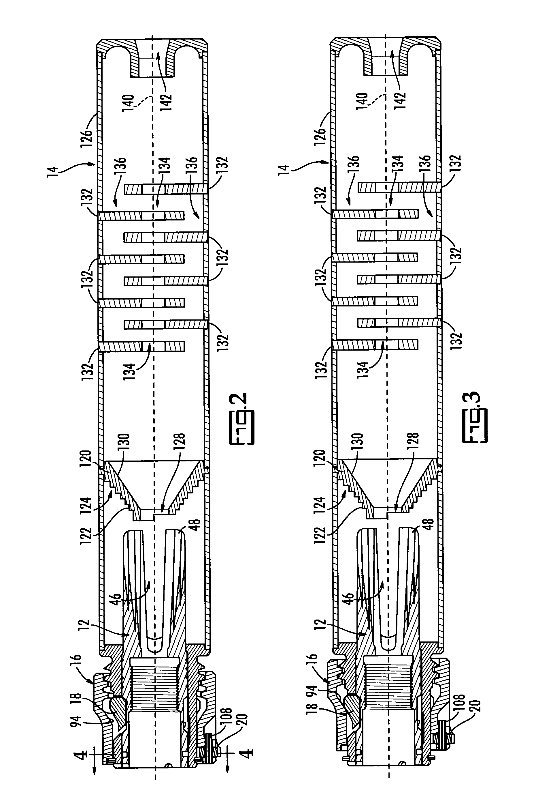
[0015]The present device is a quickly-disconnectable sound suppressor for a firearm. The device is also a quick-disconnect flash and sound suppressor for a firearm with a flash hider on the end of its barrel. Finally, the present device is a coupler for attaching a sound suppressor to a flash hider.

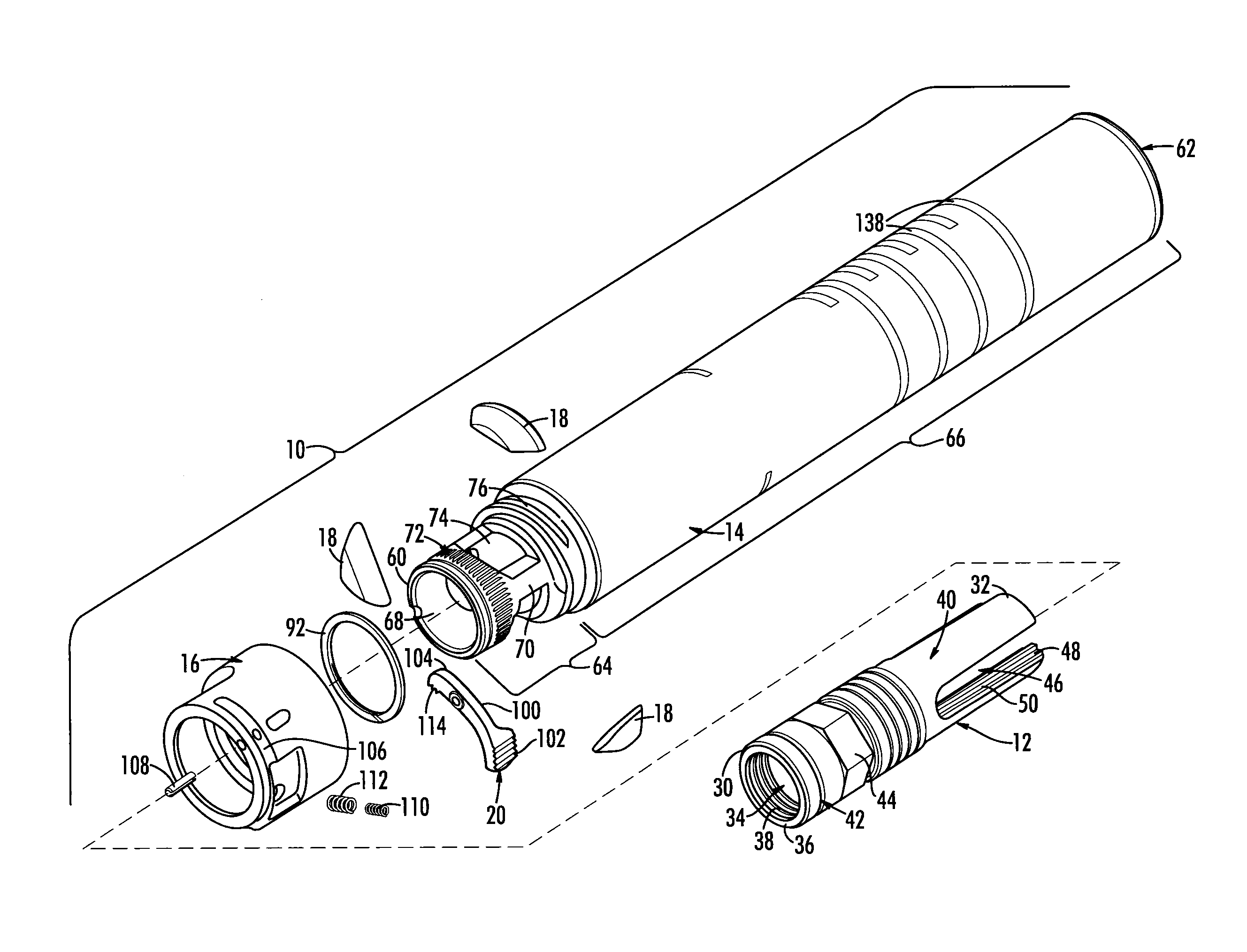
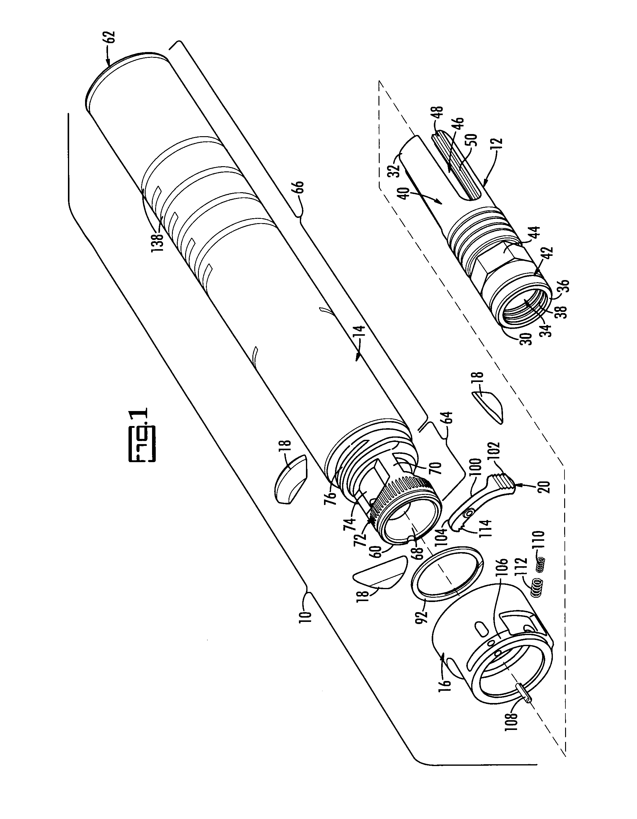
[0016]Referring now to FIGS. 1-4, FIG. 1 illustrates the components of the present flash and sound suppressor, generally indicated by reference number 10, in an exploded view. In this view, a flash hider 12 and a sound suppressor 14 are coupled by a collar 16 using plural camming latches 18 and a spring lock 20.

[0017]Flash hider 12 has a first or proximal end 30 and an opposing second or distal end 32. Flash hider 12 is essentially a tube with a central bore 34 that defines a wall 36. First end 30 has interior threads 38 that allow flash hider 12 to be threaded to the barrel of a firearm (not shown). Flash hider 12 has an exterior surface 40 that carries an annular recess 42 and, distal t...


PUM


Abstract

A flash hider, a sound suppressor and a quick-disconnect coupler that holds the sound suppressor to a flash hider is disclosed. The quick-disconnect coupler enables the suppressor to be attached to the flash hider so that the hider forms a nozzle at the entrance to the sound suppressor to facilitate the operation of the suppressor. The coupler includes a collar that threads to the first part of the suppressor over plural holes formed therein. Camming latches set in these holes are held firmly against flat surfaces on the exterior of the flash hider by the collar. A spring lock holds the collar against rotation until it is released.

Description

PRIORITY CLAIM[0001]Priority is claimed to U.S. provisional patent application Ser. No. 61 / 375,530, filed Aug. 20, 2010; to U.S. non-provisional patent application Ser. No. 13 / 032,804 filed Feb. 23, 2011, which in turn claims priority to U.S. provisional patent application Ser. No. 61 / 309,047 filed Mar. 1, 2010; to U.S. provisional patent application Ser. No. 61 / 375,339, filed Aug. 20, 2010; and to U.S. provisional patent application 61 / 375,620, filed Aug. 20, 2010, all of which are incorporated by reference herein in their entirety.BACKGROUND OF THE INVENTION[0002]A military firearm may have a flash hider threaded to the end of its barrel. The flash hider is intended to reduce both the primary flash caused by the initial explosion of the powder charge when a round of ammunition is fired, and the secondary flash caused when the partially combusted gases and hot air from the barrel reignite following the shock of meeting the colder air surrounding the end of the barrel. The visible f...

Claims


Application Information

Patent Timeline
IPC IPC(8): F41A21/00
CPCF41A21/30F41A21/34F41A21/325
Inventor MOORE, CHARLESMOOTY, THOMAS
Owner FN AMERICA
Why Eureka
Try Eureka