Latching pressure regulator

a technology of latching pressure regulator and valve valve, which is applied in the direction of valve operating means/release devices, process and machine control, etc., can solve the problems of undershoot and sluggish response, operational instability, and easy air ingestion of control elements, so as to eliminate feedback exhaust air problems and save time

Inactive Publication Date: 2013-07-23
FORD GLOBAL TECH LLC
View PDF15 Cites 0 Cited by
  • Summary
  • Abstract
  • Description
  • Claims
  • Application Information

AI Technical Summary

Benefits of technology

[0013]The regulator valve becomes latched when it bottoms out in response to opposing line pressure force against feedback pressure, thereby eliminating feedback exhaust air issues.
[0015]The system method provides an alternative to ramp down clutch pressure without causing oscillation and saving time.

Problems solved by technology

Such control elements are susceptible to air ingestion, undershoot and sluggish response, and operational instability.
Air remains in the chamber when the system is refilled, causing a high compliance, leading to overshoot, instability, and sluggish response of the regulator, and non-ideal control of clutch capacity.
This adversely affects shift quality.
A change in the worm trail may prevent air ingestion or an increase in sump level, but achieving an ideal worm trail routing is not always feasible due to packaging requirements.
Also, maintaining a high fluid level in the oil pan with a chain drive moving in the oil reduces fuel economy due to spin loss and potential aeration of oil.
Locating a regulator valve and latch valve in different layers of the main control, requires a large volume of worm trail between regulator outlet and feedback orifice, which decreases stiffness.

Method used


Image

  • Latching pressure regulator
  • Latching pressure regulator

Examples


Embodiment Construction

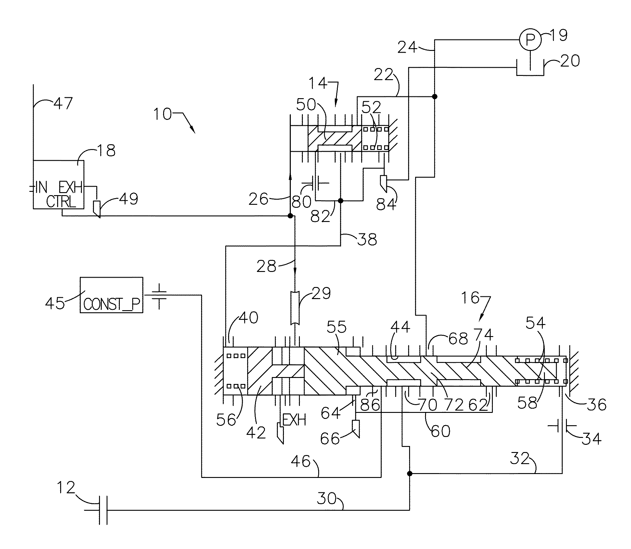
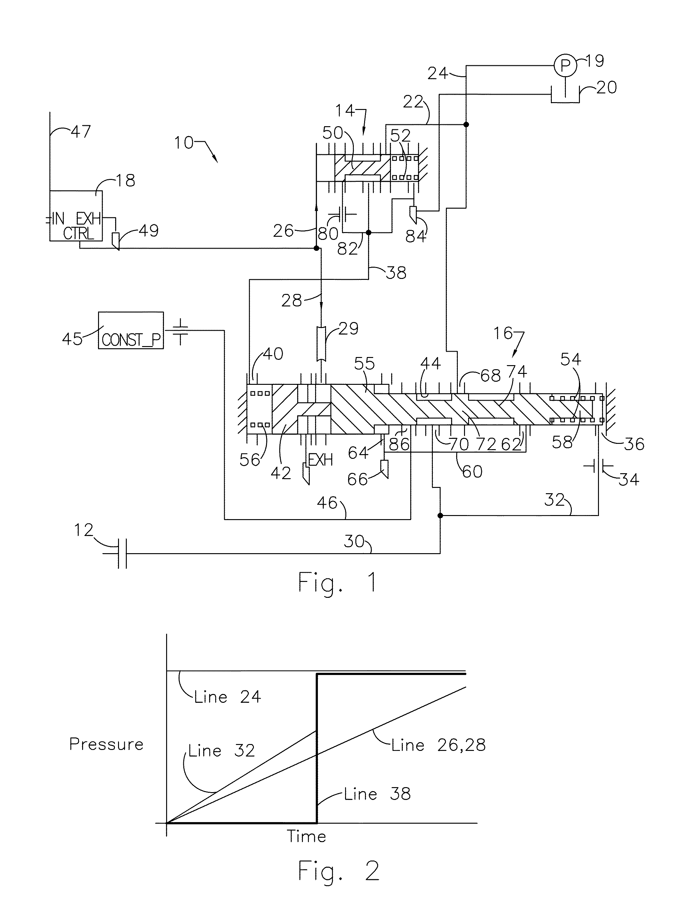
[0021]Referring now to the drawing, a portion of the hydraulic control system 10 for supplying pressurize to a friction control element, such as a clutch or brake 12, of an automatic transmission includes a latch valve 14, pressure regulator valve 16, and a control pressure valve 18, such as a variable bleed solenoid (VBS).

[0022]A pump 19 draws automatic transmission fluid (ATF) from an oil sump 20 in the transmission and delivers it at line pressure through lines 22, 24 to latch valve 14 and pressure regulator valve 16. Control pressure valve 18 is connected through line 26 to latch valve 14 and through line 28 and tube 29 to regulator valve 16. Regulated pressure, connected through line 30 to the transmission control element 12, is also carried in line 32 through orifice 34 to a feedback port 36 at one end of regulator valve 16.

[0023]When pressure in line 26 is relatively low, the state of latch valve 14 is unlatched and line pressure in line 22 is closed. When pressure in line 26...


PUM


Abstract

A system for regulating pressure supplied to a transmission control element, includes a control pressure source and line pressure source, a latch valve that opens and closes communication with the line pressure source in response to control pressure, and a regulator valve including a spool for regulating line pressure and producing control element pressure when the latch valve is closed, and an auxiliary piston responsive to line pressure and contacting the spool for connecting line pressure to the control element when the latch valve is open.

Description

BACKGROUND OF THE INVENTION[0001]1. Field of the Invention[0002]This invention relates generally to a hydraulic control system for an automatic transmission, and, more particularly, to a regulator valve and system for controlling pressure in a friction control element of the transmission.[0003]2. Description of the Prior Art[0004]A friction control element, such as a clutch or brake of an automatic transmission, can be applied and released using a combination of a regulator valve, latch valve and variable bleed solenoid (VBS) pressure in the hydraulic control circuit of the transmission.[0005]Ideally, the control system applies the clutch by an increase VBS pressure, which opens the regulator valve and allows flow to the clutch from a source of line pressure. After application of the clutch is complete and at the end of the gear ratio change, the latch valve vents feedback pressure to the regulator valve, allowing full line pressure to be directly applied to the clutch.[0006]The sys...

Claims


Application Information

Patent Timeline
Patent Type & Authority Patents(United States)
IPC IPC(8): G05D11/02
CPCF16D48/02F16H61/0206F16D2048/0221Y10T137/2567Y10T137/7754Y10T137/86582Y10T137/8663
Inventor MAHAPATRO, HRUDAYABURKHART, ROBERT O.BUTWIN, JOHN
Owner FORD GLOBAL TECH LLC
Why Eureka
Try Eureka