Electromedical implant and monitoring system including the electromedical implant

a monitoring system and electromedical technology, applied in the field of electromedical implants, can solve the problems of inability to provide therapy options for patients without monitoring implants, disadvantageous and at times cumbersome, and cardiac invasive systems are generally not suitable for patients without. , to achieve the effect of simple and reliable manner

Active Publication Date: 2013-07-23
BIOTRONIK SE & CO KG
View PDF15 Cites 1 Cited by
  • Summary
  • Abstract
  • Description
  • Claims
  • Application Information

AI Technical Summary

Benefits of technology

[0008]The invention involves an electromedical implant, particularly a pure monitoring implant, for monitoring a cardiac blood flow and an epithoracic peripheral blood flow of a living being, by which a measurement signal associated with the epithoracic peripheral blood flow can be determined in a comparatively simple and yet reliable manner. The invention also involves a monitoring system utilizing the electromedical implant, by which the pulse transit time, and preferably additional patient values derived from the pulse transit time, can be monitored and retrieved either briefly or over an extended period.

Problems solved by technology

Contrary to therapy implants, such as implantable cardiac stimulators or the like, an monitoring implant for monitoring blood flows of a living being (patient) provides no therapy options.
While such non-invasive systems have proven useful for monitoring purposes, they are disadvantageous and at times cumbersome.
However, cardiac invasive systems are generally not a suitable option for patients having no therapy indication, i.e., no (presently) defined need for therapy.
The implantation of probes in the heart, for example for determining an ECG signal using a cardiac stimulator, is complex and associated with risks for the patient.
However, this is unsuitable for patients without an electrotherapy indication.

Method used


Image

  • Electromedical implant and monitoring system including the electromedical implant
  • Electromedical implant and monitoring system including the electromedical implant
  • Electromedical implant and monitoring system including the electromedical implant

Examples


Embodiment Construction

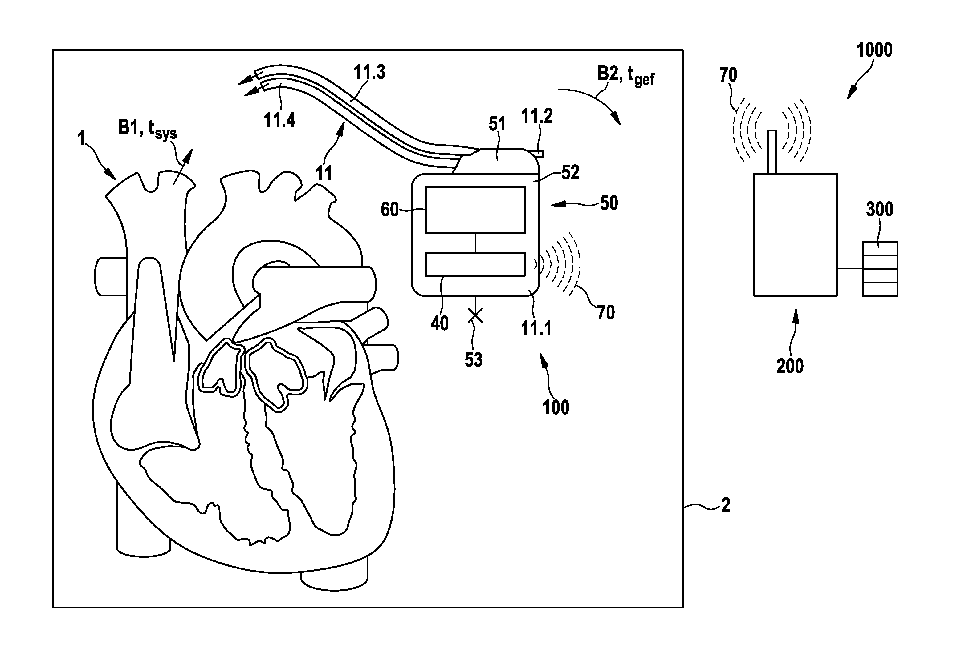
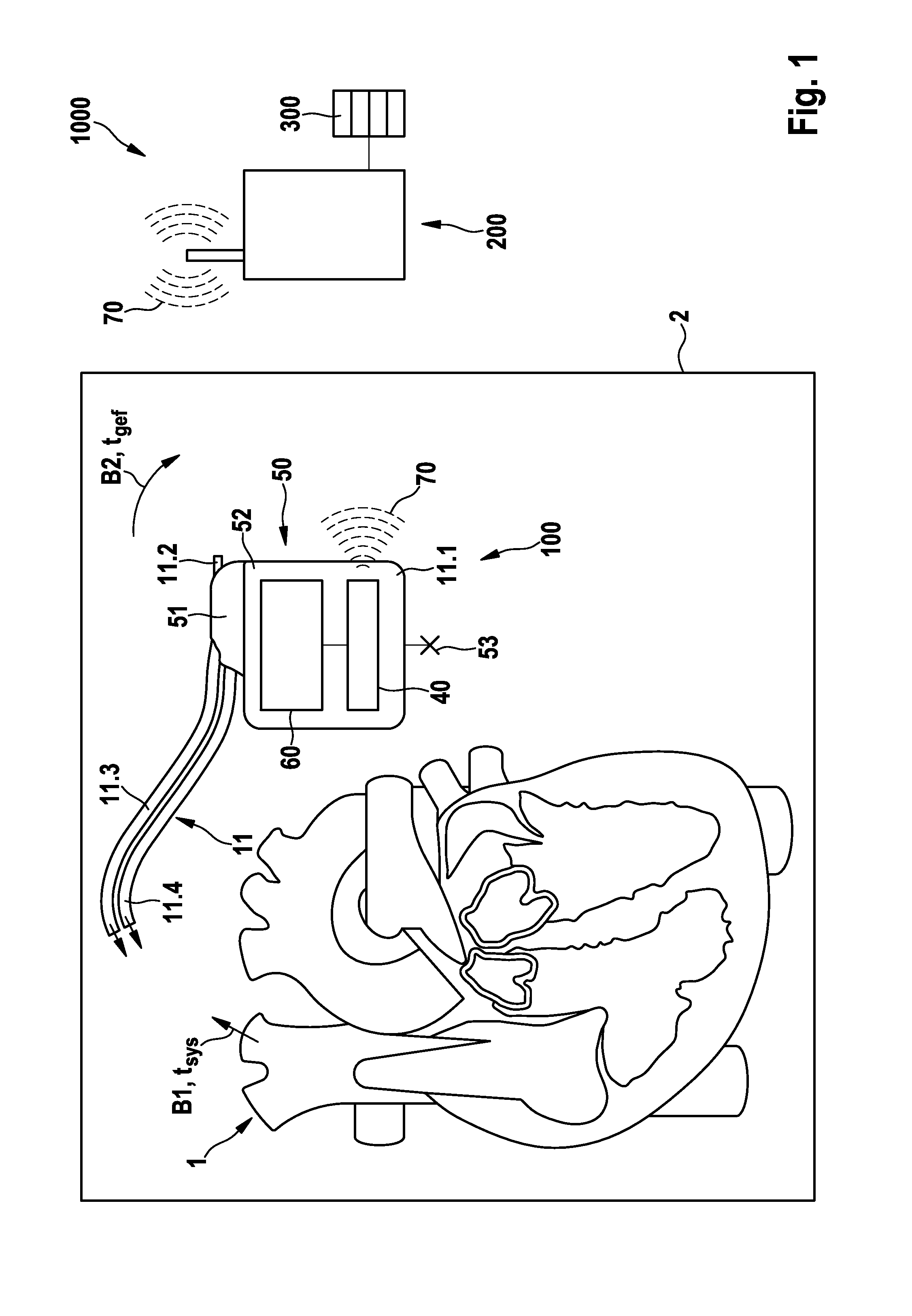
[0055]FIG. 1 schematically illustrates an exemplary preferred version of a monitoring system 1000 including an electromedical implant 100, which is equipped to monitor a cardiac blood flow B1 (conceptually illustrated by an arrow), and an epithoracic peripheral blood flow B2 of a living being (also conceptually illustrated by an arrow), the living being preferably being a patient who may or may not have a diagnosis of cardiac insufficiency. Also conceptually illustrated are the heart 1 and the thorax 2 of the patient (the thorax being represented by the box 2 about the heart 1 and the implant 100), with the blood flows B1 and B2 being shown within the thorax 2. The implant 100 is preferably designed purely as a monitoring implant, in other words, it does not perform therapy. The implant 100 includes a housing 50 having a housing container 52, a header 51, and an electrode assembly 11 connected to the housing 50. The implant 100 is situated in the thorax 2 of the patient, subcutaneou...


PUM


Abstract

An electromedical implant (100, 101, 102, 103) for monitoring a cardiac blood flow (B1) of a patient includes a detector (10, 10′, 10″) which obtains a first measurement signal (S1) associated with the cardiac blood flow (B1) and a second measurement signal (S2) associated with the epithoracic, peripheral blood flow (B2). A monitoring assembly (20) then generates a first parameter (P1) from the first measurement signal (S1) which is indicative of a time (tsys) at which blood is ejected from the heart, and a second parameter (2) from the second measurement signal (S2) which is indicative of a time (tgef) of a blood pulse in the thoracic tissue which is associated with the ejection of blood. An evaluation unit (30) then generates a pulse transit time (Δt=tgef−tsys) from the first parameter (P1) and the second parameter (P2). The detector (10, 10′, 10″) includes an impedance measuring unit (12) having an electrode assembly (11, 11′) for detection of at least the second measurement signal (S2) in the form of an impedance signal.

Description

CROSS-REFERENCE TO RELATED APPLICATIONS[0001]This application claims priority under 35 USC §119(e) to U.S. Provisional Patent Application 61 / 311,789 filed Mar. 9, 2010, the entirety of which is incorporated by reference herein.FIELD OF THE INVENTION[0002]The invention relates to an electromedical implant for monitoring a cardiac blood flow and an epithoracic, peripheral blood flow of a living being. The invention further relates to a monitoring system including the electromedical implant.BACKGROUND OF THE INVENTION[0003]An electromedical implant of the type mentioned above can be designed and / or used only for monitoring (in which case it is typically referred to as a monitoring implant), or for both monitoring and therapy (in which case it is typically referred to as a therapy implant). Contrary to therapy implants, such as implantable cardiac stimulators or the like, an monitoring implant for monitoring blood flows of a living being (patient) provides no therapy options. A monitori...

Claims


Application Information

Patent Timeline
Patent Type & Authority Patents(United States)
IPC IPC(8): A61B5/024A61B5/026
CPCA61B5/029A61B5/0295A61B5/0535A61B5/6846A61B5/721A61B5/0402A61B5/7214A61B5/7275A61B5/318
Inventor CZYGAN, GERALDLIPPERT, MICHAELSKERL, OLAF
Owner BIOTRONIK SE & CO KG
Why Eureka
Try Eureka