
Imaging systems featuring waveguiding compensation

a waveguide compensation and imaging system technology, applied in the field of in vivo imaging systems and methods, can solve the problems of inaccurate amount of agent/probe as well as its location, misleading or false attribution, and inability to accurately depict the localization and distribution of objects, etc., to achieve accurate representation of the localization and distribution

Active Publication Date: 2013-07-23
VISEN MEDICAL INC
View PDF3 Cites 4 Cited by
  • Summary
  • Abstract
  • Description
  • Claims
  • Application Information

AI Technical Summary

Benefits of technology

The invention is about systems and methods for identifying and compensating for the wiggling of electromagnetic radiation in heterogeneous crystal objects. This technology helps to get a more accurate and precise understanding of the localization and distribution of signals, reporters, or agents in such objects. By detecting and reducing these effects, the invention improves the quality of images, analysis, and reconstruction.

Problems solved by technology

This can cause misleading or false attribution of the electromagnetic radiation signal, and / or agent or probe distribution to such object regions, when such object regions might have very little or no agent or probe (including endogenous agents and exogenous agents).
The proportion or amount of agent / probe as well as its location would be inaccurate due to the waveguiding effects of electromagnetic radiation, causing artifacts in two dimensional images and tomographic images.
Regions of objects more absorbent to electromagnetic radiation might cause waveguiding or tunneling into regions of less absorption, creating inaccurate or erroneous attribution of radiative signal.
This would give rise to inaccurate and false attribution of radiation concentrated in regions vulnerable to waveguided radiation such as skin folds or other thin tissue.

Method used


Image

  • Imaging systems featuring waveguiding compensation
  • Imaging systems featuring waveguiding compensation
  • Imaging systems featuring waveguiding compensation

Examples


Embodiment Construction

[0047]It is contemplated that methods, systems, and processes described herein encompass variations and adaptations developed using information from the embodiments described herein.

[0048]Throughout the description, where systems and compositions are described as having, including, or comprising specific components, or where processes and methods are described as having, including, or comprising specific steps, it is contemplated that, additionally, there are systems and compositions of the present invention that consist essentially of, or consist of, the recited components, and that there are processes and methods of the present invention that consist essentially of, or consist of, the recited processing steps.

[0049]The mention herein of any publication, for example, in the Background section, is not an admission that the publication serves as prior art with respect to any of the claims presented herein. The Background section is presented for purposes of clarity and is not meant a...


PUM

PropertyMeasurementUnit
wavelengthaaaaaaaaaa
Riaaaaaaaaaa
emission wavelengthsaaaaaaaaaa

Abstract

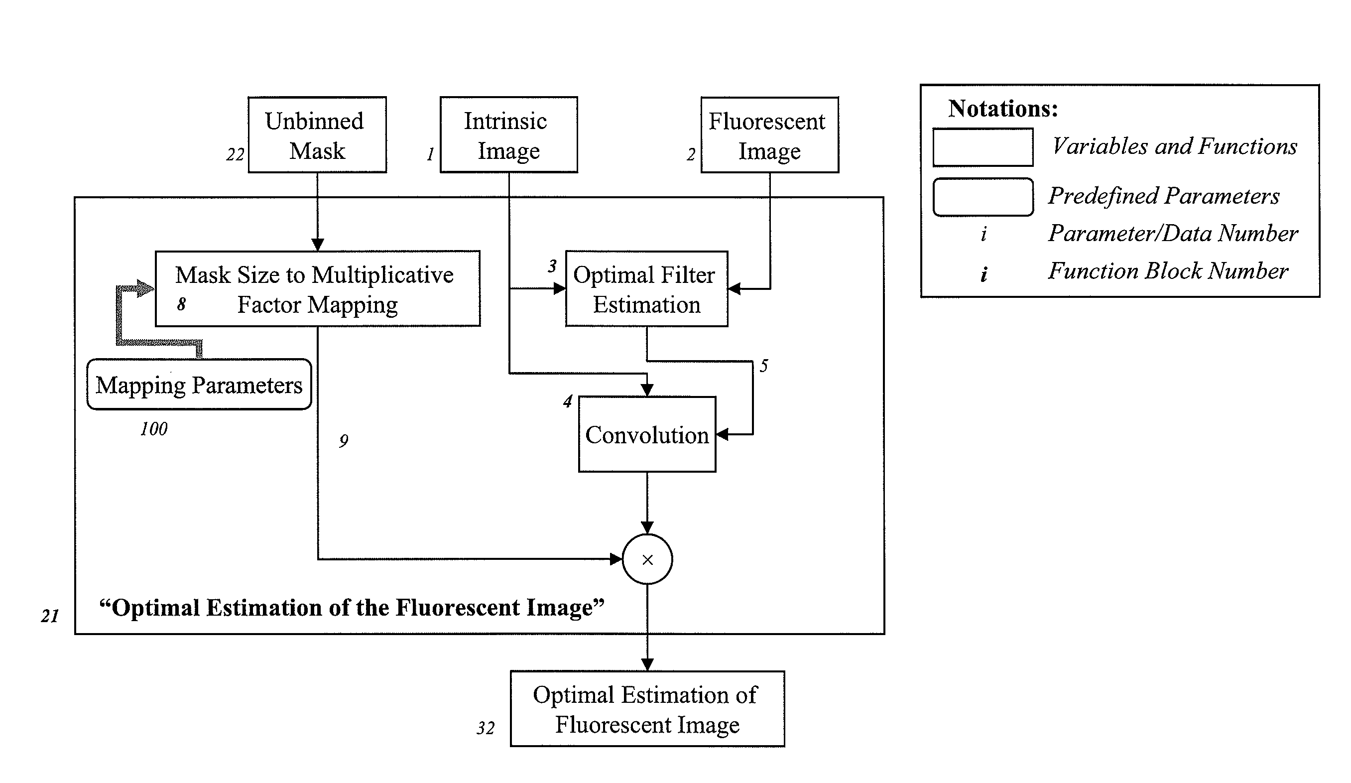
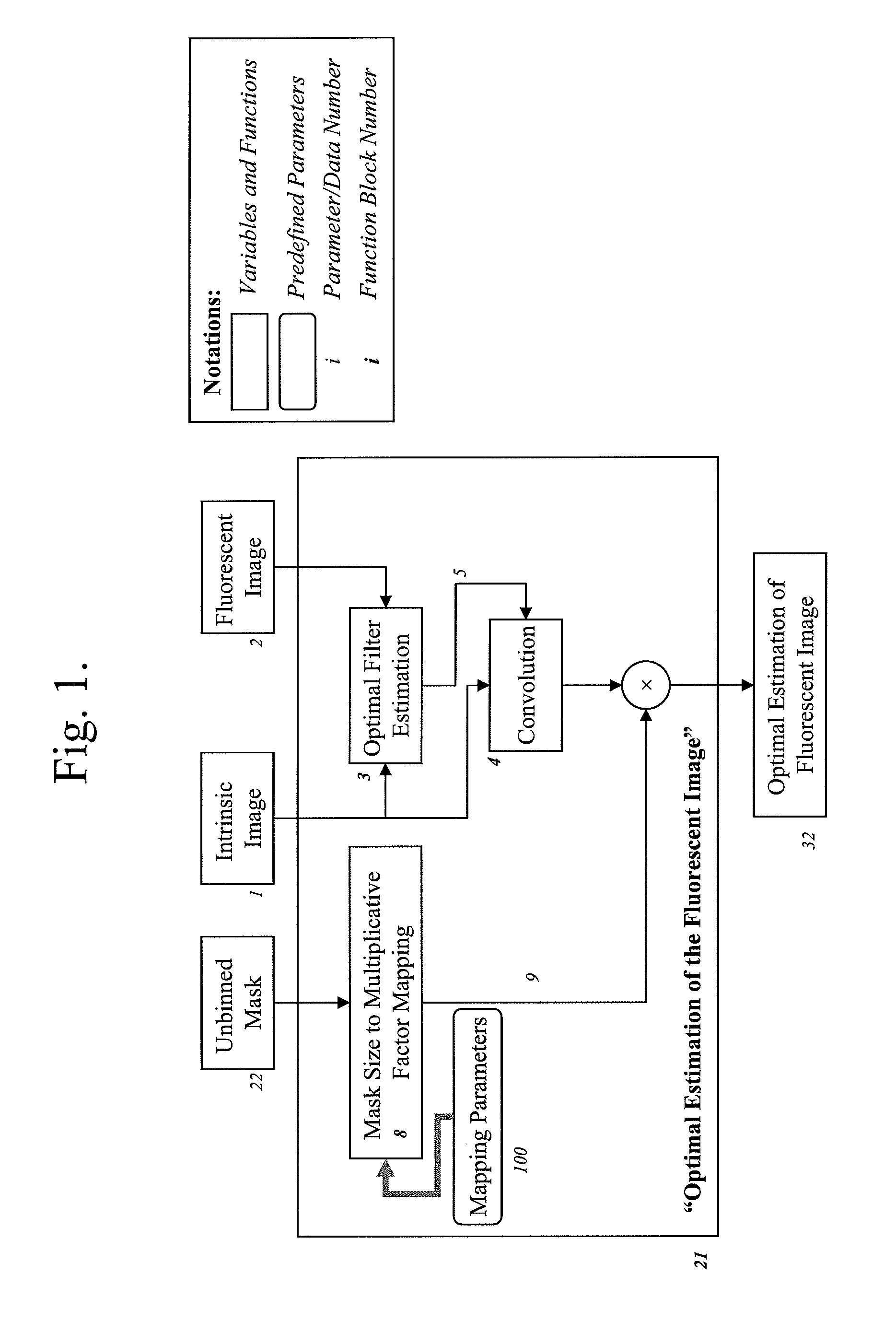
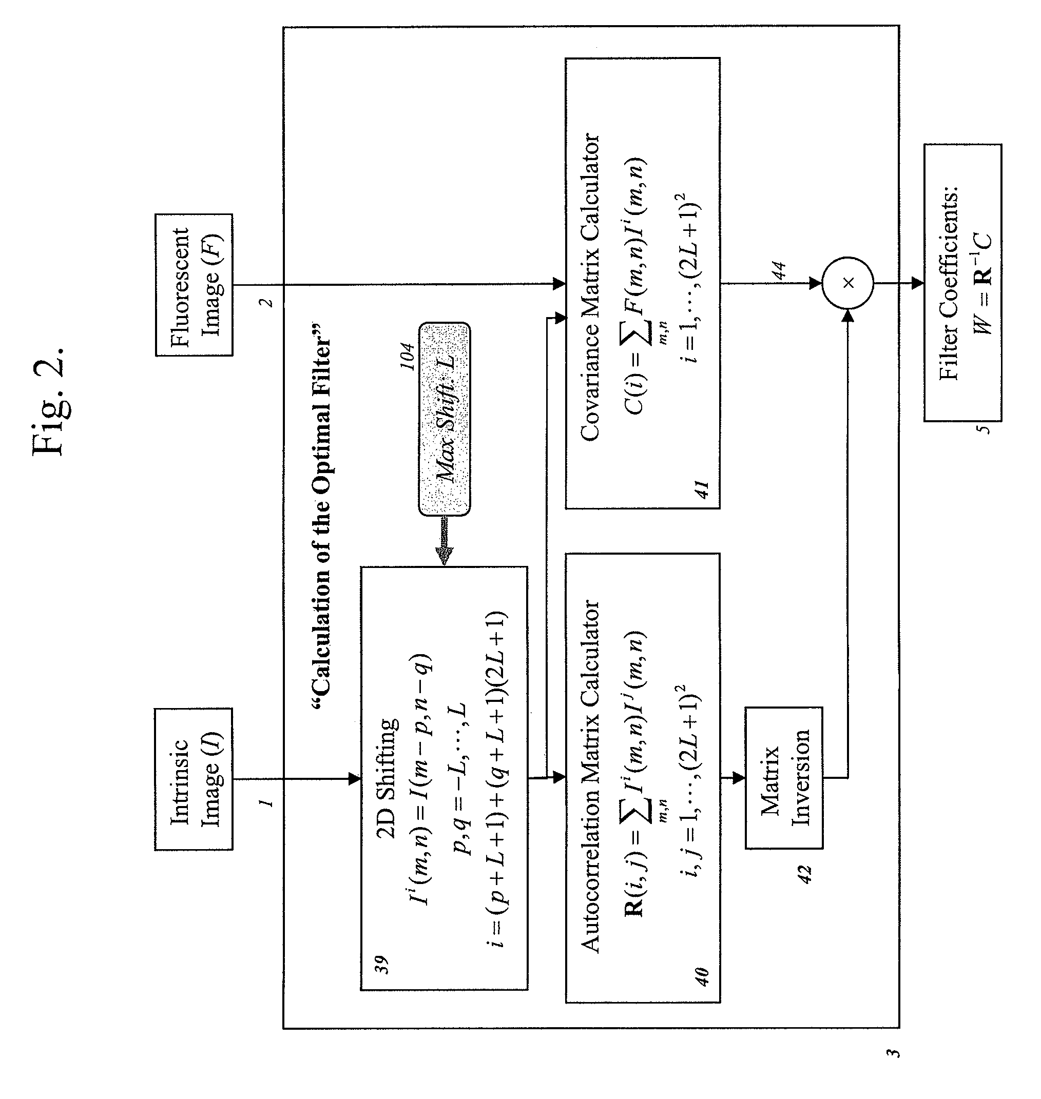
In certain embodiments, the invention relates to systems and methods for altering an image to compensate for variation in one or more physical and / or supervenient properties (e.g., optical absorption and / or scattering) in heterogeneous, diffuse tissue, thereby attenuating the effects of tissue waveguiding. The methods enable the proper identification of emission image regions that evidence waveguiding of electromagnetic radiation, and enables compensation of emission images for such waveguiding. The methods preserve the depth localization accuracy of the FMT approach and improve optical reconstruction in the targeted areas while eliminating spurious components of fluorescence from the acquired data set. Calibration methods for probe concentration mapping are also presented.

Description

RELATED APPLICATION[0001]This application is a national stage of International (PCT) Patent Application Serial No. PCT / US2008 / 065648, filed Jun. 3, 2008, and published under PCT Article 21(2) in English, which claims priority to and the benefit of U.S. provisional patent application Ser. No. 60 / 981,316, filed Oct. 19, 2007, the disclosure of which is incorporated herein by reference in its entirety.GOVERNMENT RIGHTS[0002]The invention was supported, in whole or in part, by grant 1 R44 ES012699-01 from the National Institute of Environmental Health Sciences. The Government has certain rights in the invention.FIELD OF THE INVENTION[0003]The invention relates generally to in vivo imaging systems and methods. More particularly, in certain embodiments, the invention relates to systems and methods for altering an image to compensate for variation in one or more physical and / or supervenient properties (e.g., optical absorption and / or scattering) in heterogeneous, diffuse tissue, thereby at...

Claims


Application Information

Patent Timeline
Patent Type & Authority Patents(United States)
IPC IPC(8): G01N21/64G06T7/00
CPCA61B5/0073A61B5/415G01N21/4795G01N21/6456G01N2021/6439G01N2021/6491G06T11/003A61B5/0071G06T11/005
Inventor YARED, WAEL I.MOHAJERANI, POUYANKEMPNER, JOSHUA
Owner VISEN MEDICAL INC
Learn More