Magnetic storage device

a magnetic storage and storage device technology, applied in the field of magnetic storage devices, can solve the problems of recording layer, operation failure or loss of recorded information, etc., and achieve the effect of stable operation of recording information and retention of recorded information

Inactive Publication Date: 2013-07-23
RENESAS ELECTRONICS CORP
View PDF17 Cites 97 Cited by
  • Summary
  • Abstract
  • Description
  • Claims
  • Application Information

AI Technical Summary

Benefits of technology

[0032]It is an object of the present invention which has been made in view of the above problem to provide a magnetic storage device which enables the stable operation of MRAM at the time of recording information and the stable retention of recorded information.

Problems solved by technology

In MRAM, as information is recorded by the magnetization direction of a recording layer in all of the above systems, the magnetization direction of the recording layer changes when the recording layer receives a disturbing magnetic field having a certain size or more from the outside no matter whether in operation or out of operation, thereby losing recorded information.
Therefore, in the same in-plane direction as the magnetization direction of the recording layer, the recording layer is affected even by a slight disturbing magnetic field from the outside, whereby an operation failure or the loss of recorded information is apt to occur.

Method used


Image

  • Magnetic storage device
  • Magnetic storage device
  • Magnetic storage device

Examples


Embodiment Construction

[0055]An embodiment of the present invention will be described hereinbelow with reference to the accompanying drawings.

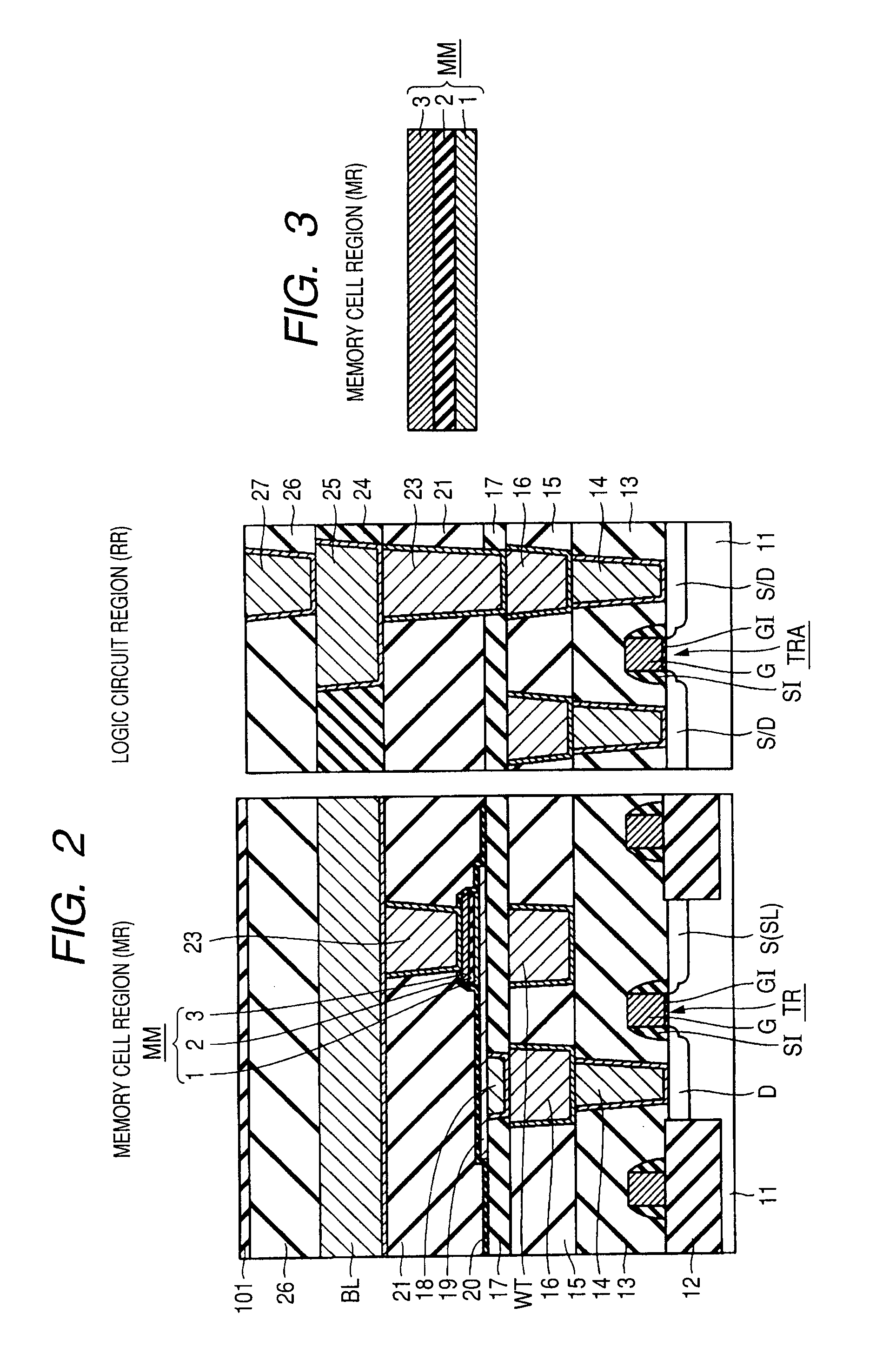
(Circuit and Structure of Memory Cell)

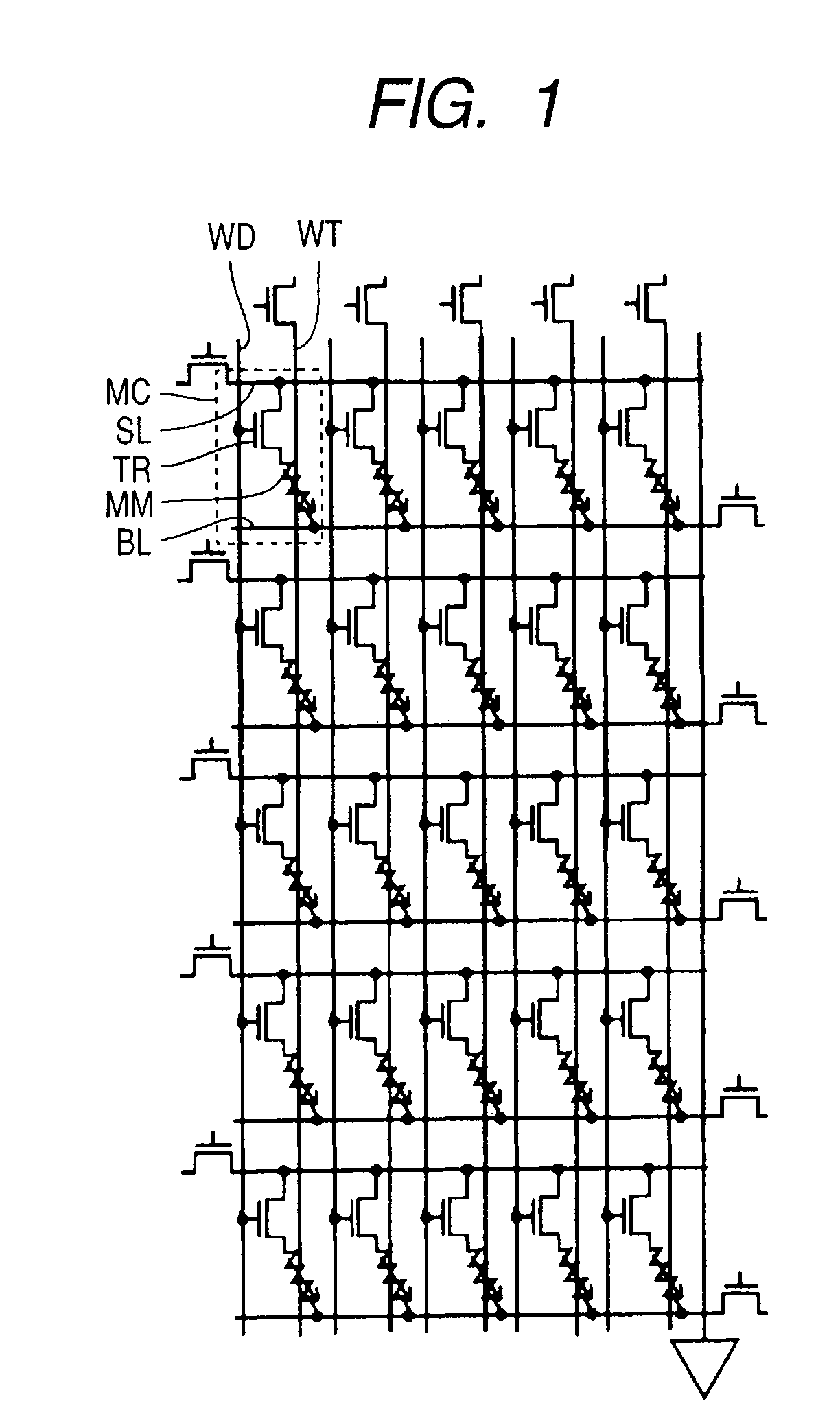
[0056]A description is first given of the circuit of the memory cell of a magnetic storage device according to the embodiment of the present invention.

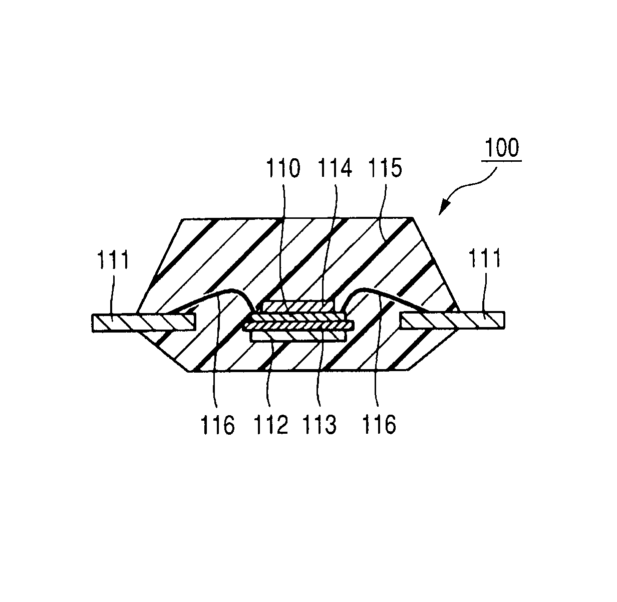
[0057]With reference to FIG. 1, in the magnetic storage device, one memory cell MC (enclosed by a dotted line) comprises an element selection transistor TR and a magnetic storage element (ferromagnetic tunnel junction element) MM. The memory cells MC are arranged in a matrix.

[0058]A write line WT and a bit line BL (first and second wirings) for writing and reading information intersect each other for the magnetic storage element MM. The write line WT extends along the magnetic storage elements MM arranged in one direction (for example, a column) but not electrically coupled to the magnetic storage elements MM. In MRAM in which the magnetization direction is controlled by a spin po...


PUM


Abstract

A magnetic storage device which enables stable operation at the time of recording information into MRAM and the stable retention of recorded information. The die of the magnetic storage device has a substrate, first and second wirings, a magnetic storage element and a first magnetic shielding structure. The first magnetic shielding structure is formed to cover the magnetic storage element in a plan view. Second and third magnetic shielding structures sandwich the die in a thickness direction. A lead frame member has the die mounted thereon and contains a ferromagnetic material. The lead frame member overlaps with only part of the die in a plan view.

Description

CROSS-REFERENCE TO RELATED APPLICATIONS[0001]The disclosure of Japanese Patent Application No. 2009-89207 filed on Apr. 1, 2009 including the specification, drawings and abstract is incorporated herein by reference in its entirety.BACKGROUND OF THE INVENTION[0002]The present invention relates to a magnetic storage device and, particularly, to a magnetic storage device having a lead frame member.[0003]A magnetoresistive effect is a phenomenon that electric resistance is changed by applying a magnetic field to a magnetic material and used in magnetic sensors and magnetic heads. Particularly, Fe / Cr and Co / Cu artificial lattice films are introduced in Non-patent Documents 1 and 2 as giant magnetoresistive (GMR) effect materials which show a very large magnetoresistive effect.[0004]There is proposed a magnetoresistive effect element which has a non-magnetic metal layer thick enough to lose an exchange coupling function between ferromagnetic layers and a laminate structure comprising a fe...

Claims


Application Information

Patent Timeline
Patent Type & Authority Patents(United States)
IPC IPC(8): H01L23/552H01L29/82G11C11/00G11C11/14
CPCG11C11/16H01L43/08H01L27/105H01L27/228H01L23/3107H01L2924/3025H01L2924/30107H01L2224/48247H01L2224/48091H01L23/49579H01L2924/00014H01L2924/00H01L2924/181G11C11/1659G11C11/1673G11C11/1675H10B61/22H10N50/10H01L2924/00012
Inventor KUROIWA, TAKEHARUTARUTANI, MASAYOSHITAKENAGA, TAKASHITAKADA, HIROSHI
Owner RENESAS ELECTRONICS CORP
Why Eureka
Try Eureka