Light emitting element, light emitting device, manufacturing method of light emitting device, and sheet-like sealing material
a technology of light emitting elements and manufacturing methods, applied in the direction of organic semiconductor devices, discharge tubes luminescnet screens, lighting and heating apparatus, etc., can solve the problem of limit on the improvement of power efficiency by the described method, and achieve the reduction of the total reflection of light which passes through the protective film, the reduction of the amount of total reflection of light, and the improvement of the light extraction efficiency of the light emitting element
- Summary
- Abstract
- Description
- Claims
- Application Information
AI Technical Summary
Benefits of technology
Problems solved by technology
Method used
Image

Examples
embodiment mode 1
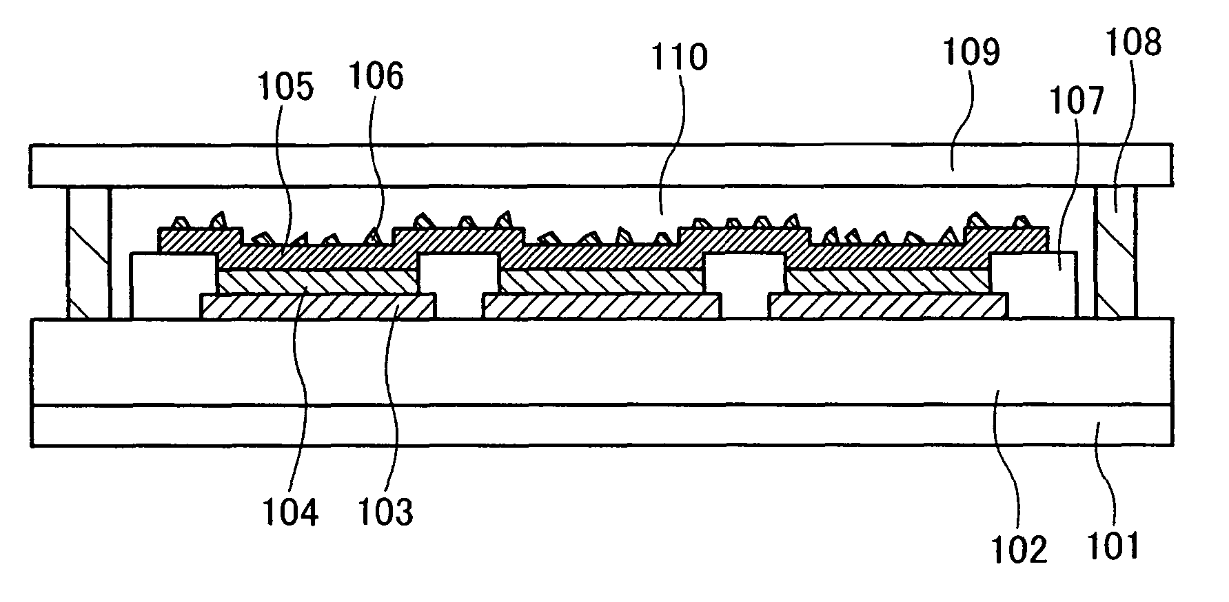
[0043]FIG. 1 is a cross sectional view of a light emitting device in which a light emitting element of this embodiment mode is provided. Over a substrate 101, a support 102 for a light emitting element is provided, and three light emitting elements are provided over the support 102.
[0044]In each light emitting element, a first electrode 103, a light emitting layer 104, and a second electrode 105 are sequentially stacked over the substrate 101. A plurality of fine particles 106 is provided on the second electrode 105, in contact with a surface of the second electrode 105. Note that the second electrode 105 is commonly provided for the three light emitting elements. An insulating layer 107 is provided for separating the light emitting elements each other, and is often called a partition wall.
[0045]A sealing substrate 109 is fixed to the substrate 101 with a sealing material 108 which is provided to surround a perimeter of the substrate 101, thereby sealing the light emitting elements....
embodiment mode 2
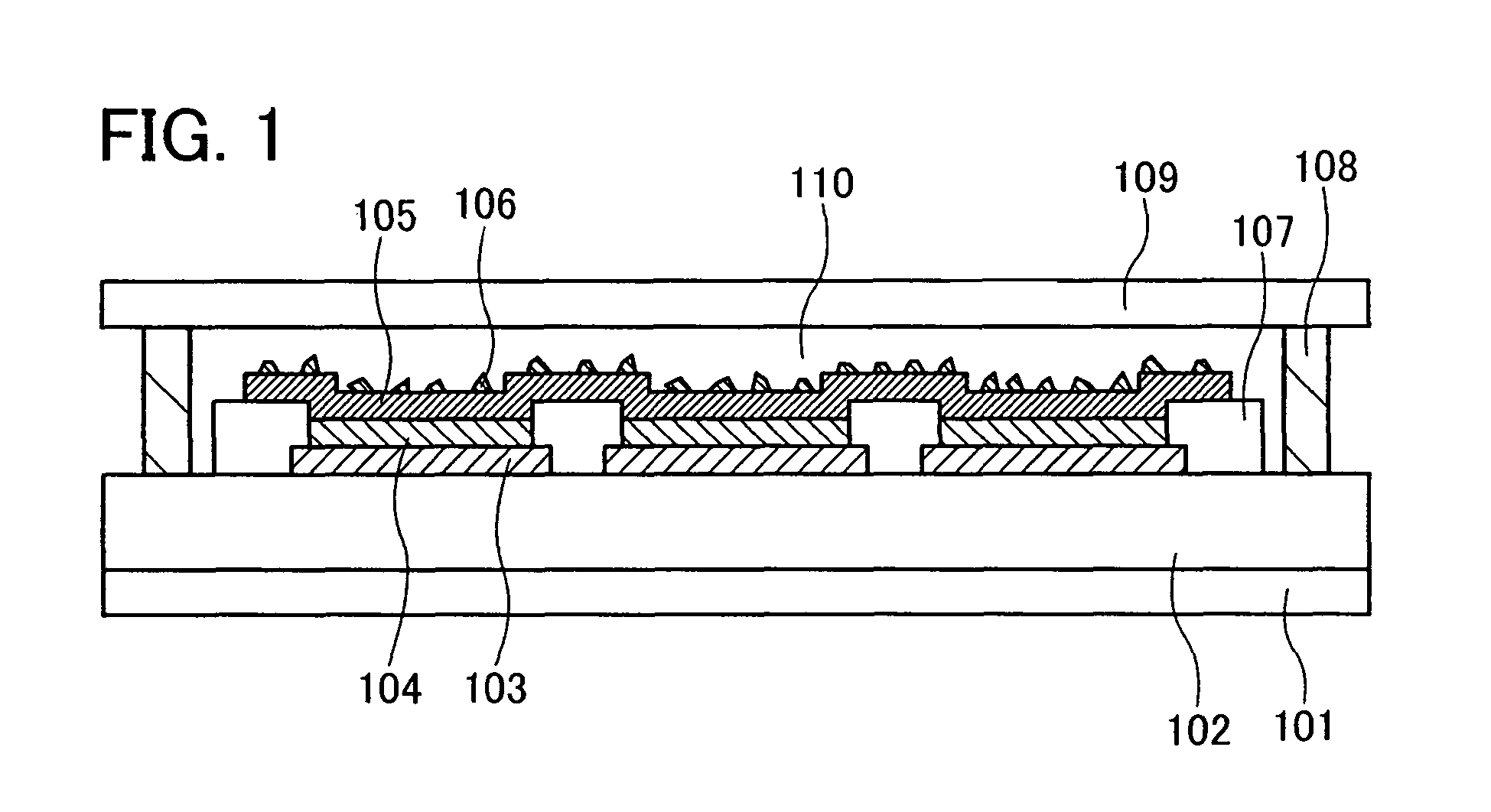
[0075]Embodiment Mode 2 will be described with reference to FIGS. 2A to 2D. The air-sealed space between the substrate 101 and the substrate 109 is filled with a gas in Embodiment Mode 1. However, in a light emitting device of this embodiment mode, the space is filled with a solid material which is prepared by filling a liquid-phase material and curing it. A sealing structure of a light emitting device in which a solid is provided between substrates is called a solid sealing structure, and this word is frequently used to distinguish it from the structure in which a gas is filled. In this specification, this word will be used to distinguish the structure in which a solid is provided between substrates from the structure in which a gas is filled.
[0076]By applying the process described in Embodiment Mode 1, a substrate 101 over which fine particles 106 are sprayed on a surface of a second electrode 105 is prepared (FIG. 2A).
[0077]Next, an uncured sealing material 108 is provided with a...
embodiment mode 3
[0080]Embodiment Mode 3 will be described with reference to FIGS. 3A to 3C. This embodiment mode will also describe a light emitting device having a solid sealing structure similar to Embodiment Mode 2.
[0081]By the process described in Embodiment Mode 1, a substrate 101 over which light emitting elements each including a first electrode 103, a light emitting layer 104, and a second electrode 105 are formed over a support 102 is prepared. In addition, before spraying fine particles, a sealing material 108 is provided on a perimeter of the substrate 101 as described in Embodiment Mode 1 (FIG. 3A).
[0082]An uncured (liquid-phase) filler 302 in which fine particles 106 are dispersed is prepared. As a material of the filler 302, similar materials to those of the filler 201 of Embodiment Mode 2 can be used. In a region surrounded by the sealing material 108, the uncured filler 302 in which the fine particles 106 are dispersed is dropwised (FIG. 3B).
[0083]The substrate 109 is provided over ...
PUM
 Abstract
Description
Claims
Application Information
 - R&D
- Intellectual Property
- Life Sciences
- Materials
- Tech Scout
- Unparalleled Data Quality
- Higher Quality Content
- 60% Fewer Hallucinations
Browse by: Latest US Patents, China's latest patents, Technical Efficacy Thesaurus, Application Domain, Technology Topic, Popular Technical Reports.
© 2025 PatSnap. All rights reserved.Legal|Privacy policy|Modern Slavery Act Transparency Statement|Sitemap|About US| Contact US: help@patsnap.com