
System and method for color-specific sequence scaling for sequential color systems

a color sequence and color technology, applied in the field of image display systems, can solve the problems of inability to change the sequence of colors or their relative duration, memory storage requirements (and associated costs), and achieve the effects of reducing storage requirements for color sequences, hardware and software requirements, and precise control of color cycle times

Active Publication Date: 2013-07-23
TEXAS INSTR INC
View PDF18 Cites 2 Cited by
  • Summary
  • Abstract
  • Description
  • Claims
  • Application Information

AI Technical Summary

Benefits of technology

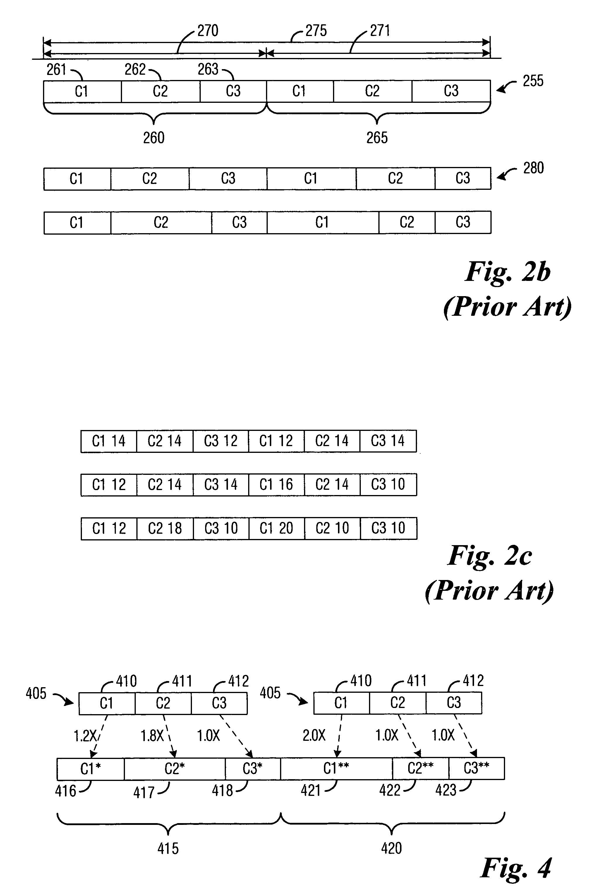
[0017]An advantage of a preferred embodiment of the present invention is that the storage requirements for the color sequences can be significantly reduced by storing a unique color sequence descriptor for each type of color sequence and generating all needed color sequences from the unique color sequence descriptor. This allows for the storage of a small number of color sequence descriptors rather than hundreds if not thousands of color sequences.
[0018]Another advantage of a preferred embodiment of the present invention is a more precise control of the color cycle times, which can yield images with actual chromatic characteristics that are closer to the intended chromatic characteristics.
[0019]A further advantage of a preferred embodiment of the present invention is that the hardware and software requirements for implementing the present invention are very small, which can reduce the costs associated with implementing the present invention in products.

Problems solved by technology

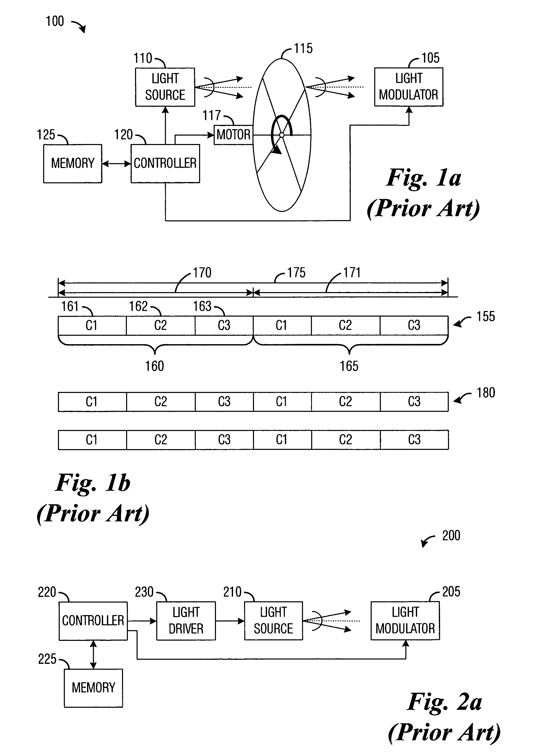
Since the color wheel is a physical entity, it is not possible to change the sequence of colors or their relative durations once the color wheel has been manufactured.
One disadvantage of the prior art is that although the use of rapidly switching light sources can enable changes in color sequences, it has been necessary to store the color sequence information in the memory of the display system.
Given a potentially large number of color sequences, the memory storage requirements (and associated costs) can be significant.

Method used


Image

  • System and method for color-specific sequence scaling for sequential color systems
  • System and method for color-specific sequence scaling for sequential color systems
  • System and method for color-specific sequence scaling for sequential color systems

Examples


Embodiment Construction

[0028]The making and using of the presently preferred embodiments are discussed in detail below. It should be appreciated, however, that the present invention provides many applicable inventive concepts that can be embodied in a wide variety of specific contexts. The specific embodiments discussed are merely illustrative of specific ways to make and use the invention, and do not limit the scope of the invention.

[0029]The present invention will be described with respect to preferred embodiments in a specific context, namely a sequential color display system utilizing a DMD (digital micromirror device) as a spatial light modulator. The invention may also be applied, however, to other sequential color display systems, such as those using deformable mirror, reflective liquid crystal, liquid crystal on silicon, and so forth, display technologies.

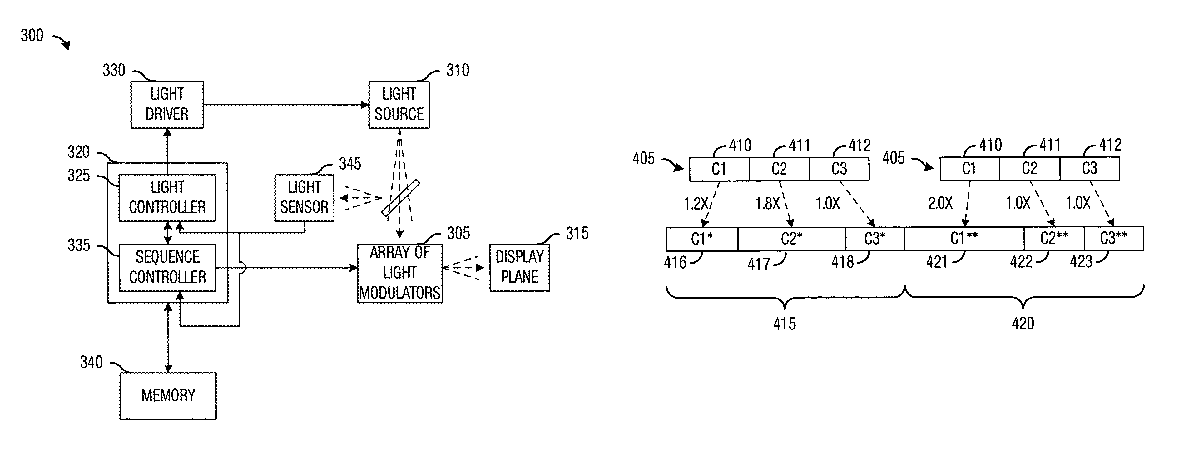
[0030]With reference now to FIG. 3, there is shown an exemplary display system 300, according to a preferred embodiment of the present invention...


PUM


Abstract

System and method for adjusting the color segment durations for colors in a color sequence in sequential color display systems. A preferred embodiment comprises receiving a desired color sequence to display, computing a scaling factor for each color in the desired color sequence based on a reference color sequence, and sequentially displaying the colors in the desired color sequence. The reference color sequence used in computing the scaling factors specifies a duration for each color in the reference color sequence, while the desired color sequence specifies a desired duration for each color in the desired color sequence. The use of a single reference color sequence to create a large number of color sequences can save a significant amount of storage space and can allow for the storage of reference color sequences to meet varying chromatic properties due to changes in the display system, user settings, and operating environment.

Description

TECHNICAL FIELD[0001]The present invention relates generally to a system and method for image display systems, and more particularly to a system and method for adjusting the color segment durations for colors in a color sequence in sequential color display systems.BACKGROUND[0002]An example of a sequential color display system is a display system that utilizes a digital micromirror device (DMD) to produce images for display purposes. A DMD is a type of spatial light modulator that uses a large number of micromirrors arranged in an array. Each micromirror typically pivots about an axis and can reflect light from a light source either onto a display plane or away from the display plane, with the position (state) of the micromirrors in the DMD being dependent on the image being displayed. The image on the display plane is created by the micromirrors operating in conjunction with one another.[0003]The DMD is normally a binary spatial light modulator, i.e., the light from the light sourc...

Claims


Application Information

Patent Timeline
Patent Type & Authority Patents(United States)
IPC IPC(8): G09G3/00G09G3/36
CPCG09G3/3413G09G2310/0235G09G2320/062G09G2360/145G09G2360/16
Inventor DICKINSON, LARRY D.
Owner TEXAS INSTR INC
Learn More