Expanded four fiber unit cable for increased fiber count cables having increased flexibility and fiber strength utilization

a fiber count and fiber technology, applied in the field of fiber optic cables, can solve the problems of increasing the rigidity of high fiber count cables, and increasing the difficulty of bending, so as to increase flexibility, reduce stiffness, and increase the fiber count

Active Publication Date: 2013-07-23
BERK TEK
View PDF7 Cites 25 Cited by
  • Summary
  • Abstract
  • Description
  • Claims
  • Application Information

AI Technical Summary

Benefits of technology

[0009]The present arrangement provides a compact high fiber count fiber optic cable for use for example in server farms or in fiber-to-home applications that requires a increased flexibility, reduced stiffness, inherently less stress on the fiber, and smaller diameter than prior art solutions. The cable has a reduced outer diameter (with little or no added strength members) with minimal induced stress on the fibers, while retaining good buffer tube stripabilty.
[0011]In one arrangement, the use of basic units composed of four fibers per buffer tube maintains good fiber / cable flexibility, as this design prevents fiber cross over during cable flexion.
[0012]Moreover, when using many four fiber / per tube sub-units, each tube is stranded together into larger high fiber count cables. The overall cable arrangement allows the fibers themselves to be uniformly stressed so that they act in concert to fully utilize the fiber strength and meet the necessary strength requirements using the fiber strength alone, without the need for any added strength members.
[0013]In another embodiment, the use of an additional mold-release / release / slip agent on the fibers within the buffer tube allows the cable to maintain tube stripability requirements even with the tighter buffer tubes. (stripability refers to a test that measures the ability to mechanically remove the tube for a certain distance without exceeding a threshold force)

Problems solved by technology

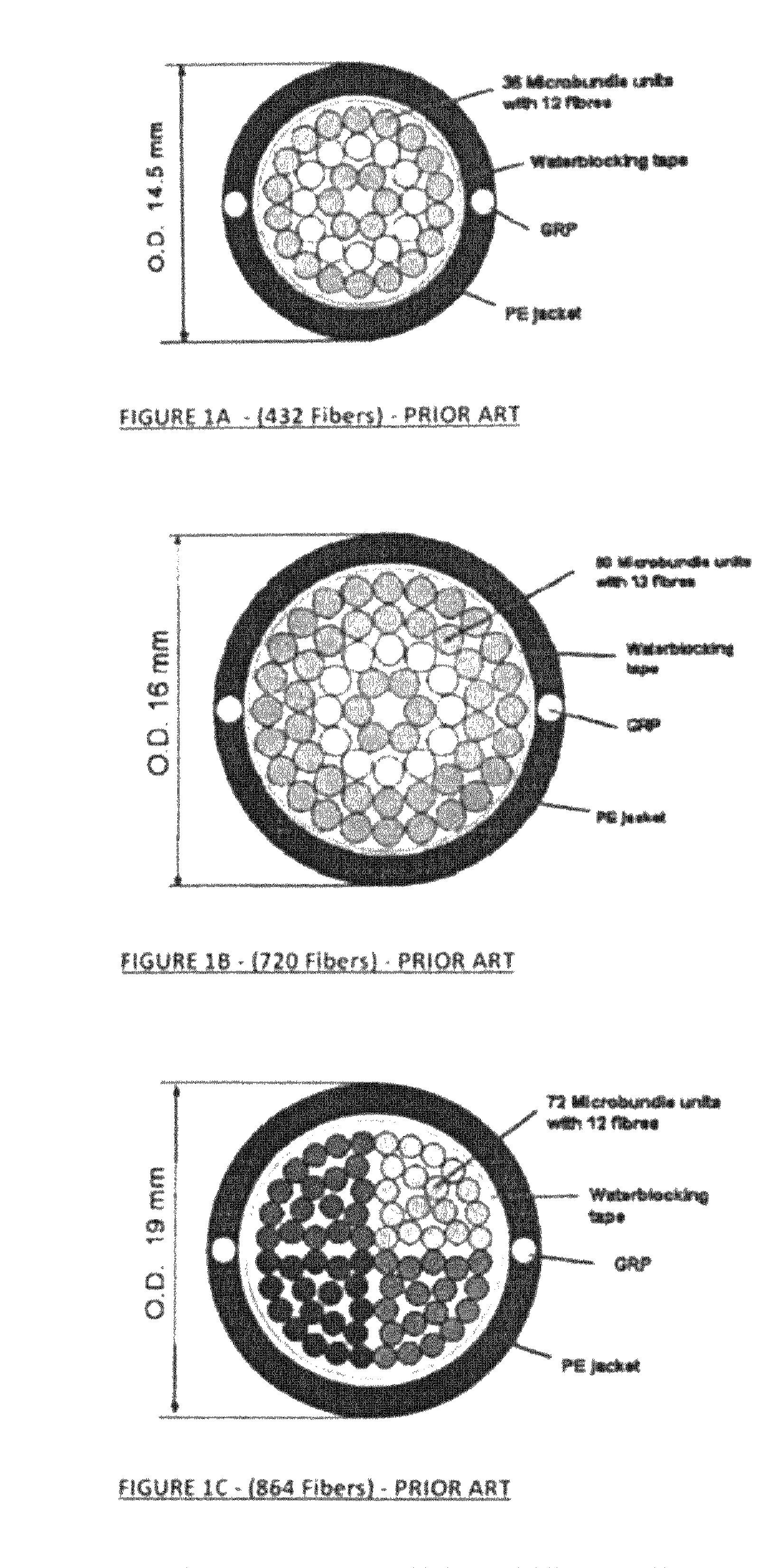
Other arrangements having tight bundles of twelve fiber units have been tried, but such arrangements require highly bend resistant fibers because of the stresses inherent to such fiber groupings.
The highly bend resistant fibers mask the inherent stress on the fiber in this design and may result in fiber breaks over the long term.
Although this may have certain stability advantages, it tends to make these high fiber count cables even stiffer and more difficult to bend.
Thus, although the optical cables are otherwise functional, they are not well suited to confined spaces that often require tight bending, even though there is a large need for such high fiber count cables in server farms and other such confined spaces.
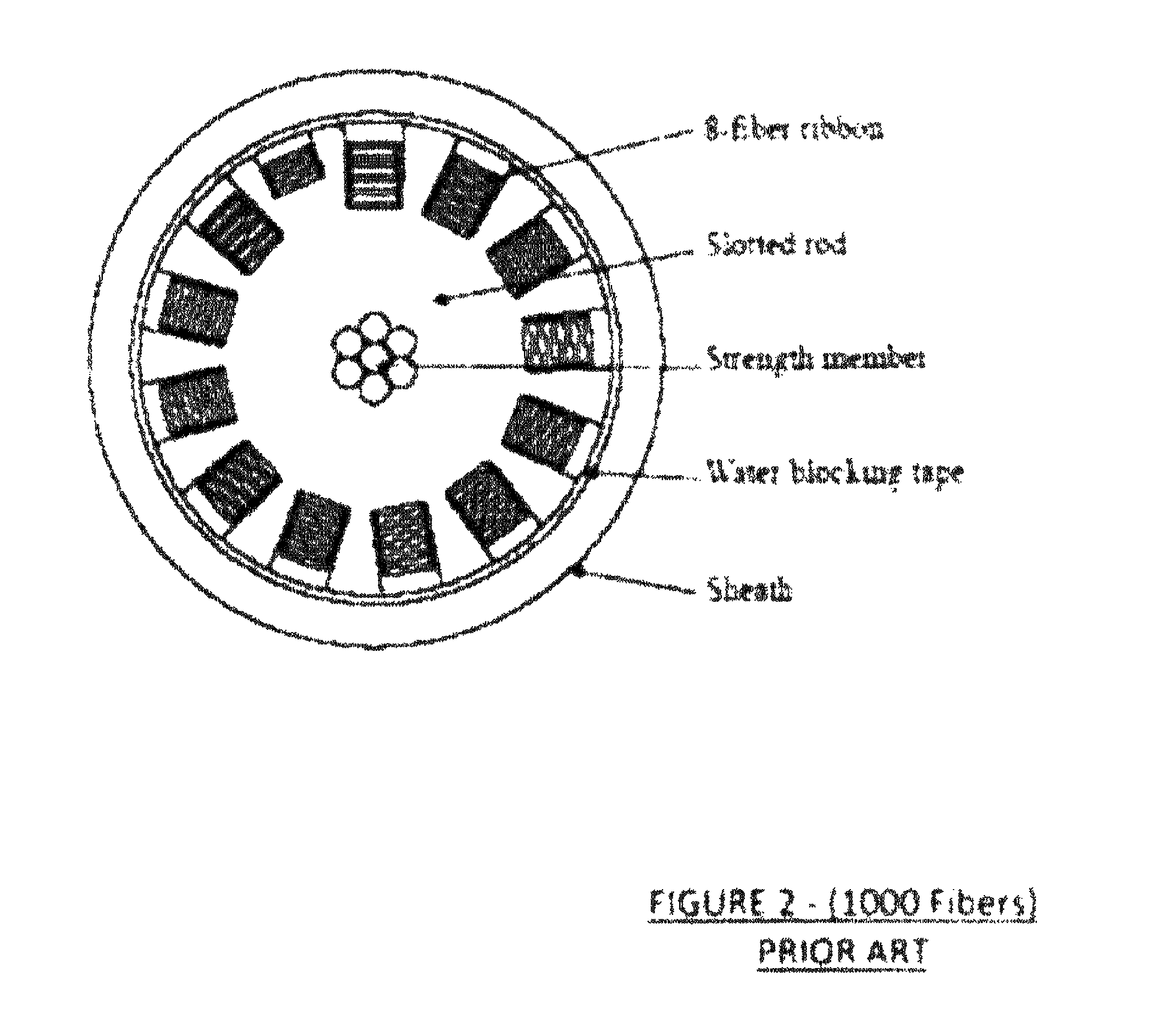
This arrangement results in a stiff cable due to its shape and dimensions.

Method used


Image

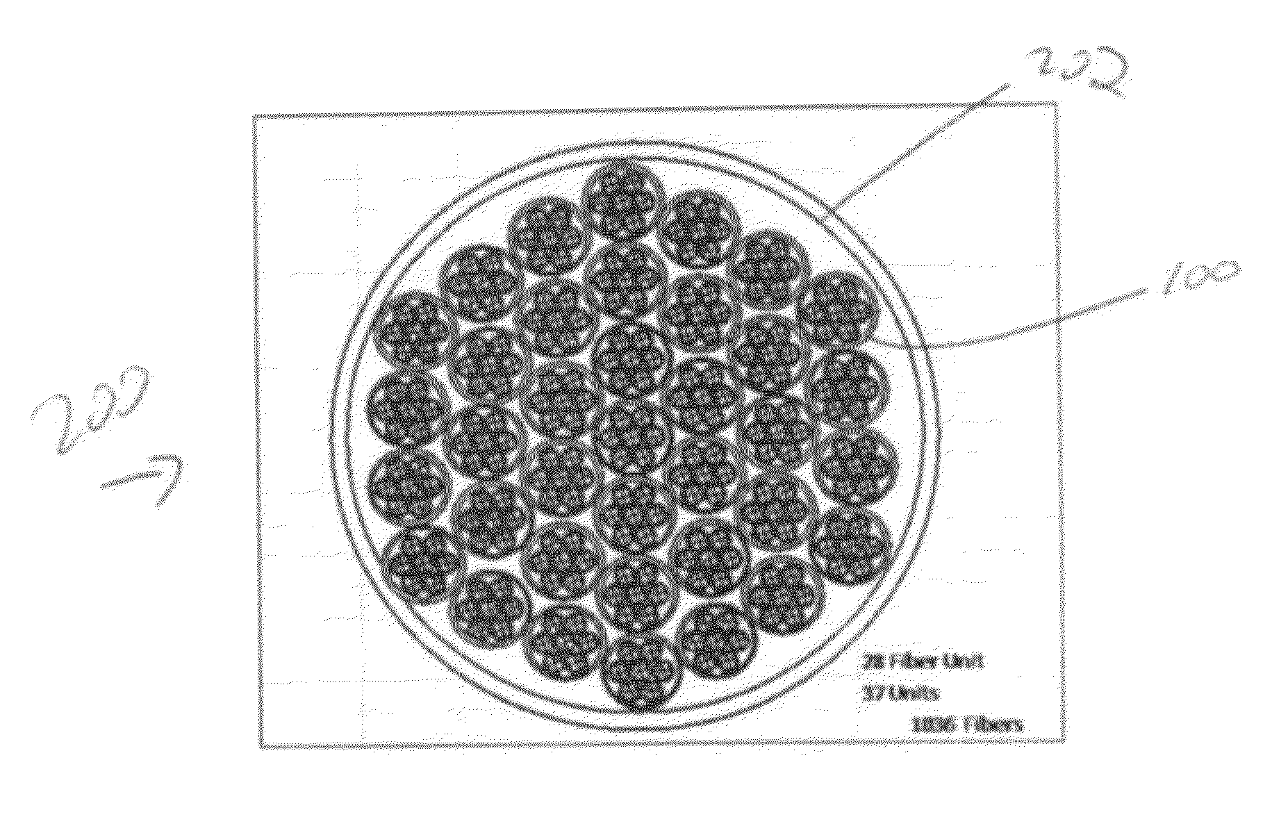
  • Expanded four fiber unit cable for increased fiber count cables having increased flexibility and fiber strength utilization
  • Expanded four fiber unit cable for increased fiber count cables having increased flexibility and fiber strength utilization
  • Expanded four fiber unit cable for increased fiber count cables having increased flexibility and fiber strength utilization

Examples


Embodiment Construction

[0023]In one embodiment as shown in FIG. 3 a basic subunit 10 is shown having four fibers 12 inside. In the present arrangement fibers 12 are typical UV coated optical fibers with 250 microns (0.25 mm) diameter. However, larger tight buffer fibers (600 micron to 900 micron) may also be used in each of the below described cables. Fibers 12 may have a typical tensile rating requiring about 430 grams of tension to reach the typical safe elongation target of 0.5%, however they may be of later designs that can withstand 0.6% to 1% elongation (under even greater grams of tension).

[0024]Around the four squarely arranged fibers 12, is a polymer jacket 14 to form subunit 10. Jacket 14 may be made from PVDF (Polyvinylidene Fluoride) or FEP (Fluorinated Ethylene Polymer), or other non-halogenated polymers including polypropylene (PP), FRPVC (Fire Resistant Polyvinyl Chloride) or polyethylene (PE) that have good fire resistant properties (such as FR versions of PE or PP). This polymer selection...


PUM


Abstract

A fiber optic cable includes a plurality of optical fiber subunits, each of the subunits including four fiber optic elements and an enclosing jacket. A plurality of optical fiber subunit assemblies are also included, each of which includes a plurality of the optical fiber subunits and an enclosing micro-sheath. The subunits are stranded around one another. A sheath encloses the plurality of optical fiber subunit assemblies.

Description

FIELD OF THE INVENTION[0001]The present application relates to fiber optic cables. More particularly, the present application relates to the construction of large fiber optic cables.DESCRIPTION OF RELATED ART[0002]Currently high fiber count cables (e.g. containing over 100 fibers) tend to have larger outer diameters and are typically constructed in robust manner. For example, such cables may be constructed as ribbon cables having stacks of ribbons or loose fibers in slotted cores or large tubes.[0003]Other arrangements having tight bundles of twelve fiber units have been tried, but such arrangements require highly bend resistant fibers because of the stresses inherent to such fiber groupings. The highly bend resistant fibers mask the inherent stress on the fiber in this design and may result in fiber breaks over the long term.[0004]Additionally, in an attempt to reduce the stress on the ribbons or tight bundles of twelve fiber units, strength members are utilized. Although this may ...

Claims


Application Information

Patent Timeline
Patent Type & Authority Patents(United States)
IPC IPC(8): G02B6/44
CPCG02B6/4411G02B6/4482
Inventor KELLER, DAVIDROSENQUIST, JEFF
Owner BERK TEK
Why Eureka
Try Eureka