
Efficient data management for shell finite elements representing layered composite materials

a composite material and data management technology, applied in the field of computer-aided engineering analysis, can solve the problems of prior art approaches, manual and/or semi-manual ad-hoc, and inconvenient use for users, and achieve the effects of reducing the complexity of the user experience, and reducing the cost of the user experien

Active Publication Date: 2013-07-23
ANSYS
View PDF19 Cites 8 Cited by
  • Summary
  • Abstract
  • Description
  • Claims
  • Application Information

AI Technical Summary

Problems solved by technology

An aircraft made of pure metal could fail catastrophically if a small crack appeared in the skin of the airplane.
However, there is a problem for prior art approaches.
In particular, this problem occurs when a large number of different composite materials are used in a structure (e.g., modern aircraft) or when the number of layers and their material properties change continuously throughout a given structural component.
For example, the prior art approach is tedious, manual and / or semi-manual ad-hoc and often confusing for the user.
Not only is the prior art approach time-consuming, it is also error-prone and requires additional effort when the computation output is analyzed.
A related problem associated with the prior art approach is that efficient computer processing techniques such as vectorization and domain decomposition in massive parallel processing cannot be applied optimally when parts use layered composite materials that vary continuously in the number of layers and material properties.
In composite shell finite elements, the time required to process each shell element is proportion to the number of layers which can lead to unbalanced processor loads depending upon the element distribution in the FEA model.

Method used


Image

  • Efficient data management for shell finite elements representing layered composite materials
  • Efficient data management for shell finite elements representing layered composite materials
  • Efficient data management for shell finite elements representing layered composite materials

Examples


Embodiment Construction

[0020]In the following description, numerous specific details are set forth in order to provide a thorough understanding of the present invention. However, it will become obvious to those skilled in the art that the present invention may be practiced without these specific details. The descriptions and representations herein are the common means used by those experienced or skilled in the art to most effectively convey the substance of their work to others skilled in the art. In other instances, well-known methods, procedures, components, and circuitry have not been described in detail to avoid unnecessarily obscuring aspects of the present invention.

[0021]Reference herein to “one embodiment” or “an embodiment” means that a particular feature, structure, or characteristic described in connection with the embodiment can be included in at least one embodiment of the invention. The appearances of the phrase “in one embodiment” in various places in the specification are not necessarily ...


PUM

PropertyMeasurementUnit
time-marching simulationaaaaaaaaaa
time-aaaaaaaaaa
thicknessaaaaaaaaaa

Abstract

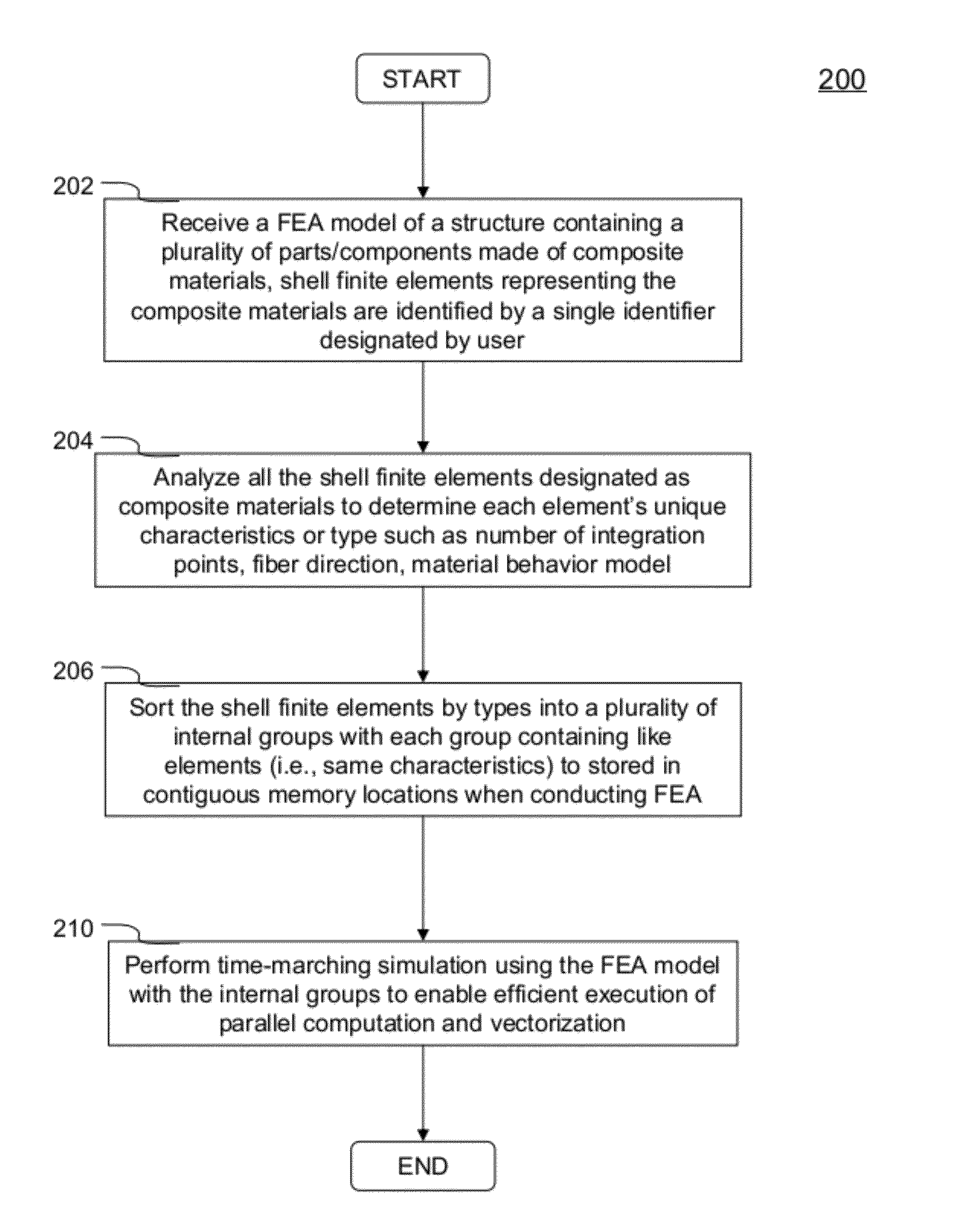
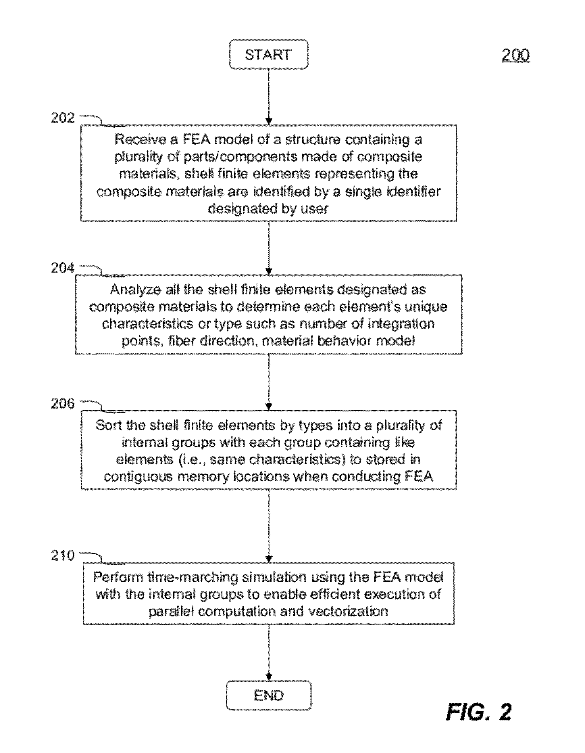
Methods and systems for obtaining numerically simulated structural behaviors of layered composite materials within a structure in a time-marching simulation using finite element analysis (FEA) are disclosed. A single identifier is used for designating all shell finite elements representing parts or components made of layered composite materials in a FEA model of a structure by user. Layered composite materials may have arbitrary number of layers. Each layer may have different material orientation / angle or fiber direction, thickness, and structural material behaviors. Each shell element representing composite material includes a set of through-thickness integration points with each corresponding to one layer of the layered composite materials. The shell elements are sorted by types into a number of internal groups to facilitate vectorization and / or more optimal domain decomposition in massive parallel processing. The internal groups are configured to be hidden from the user and stored in contiguous memory locations when conducting a FEA.

Description

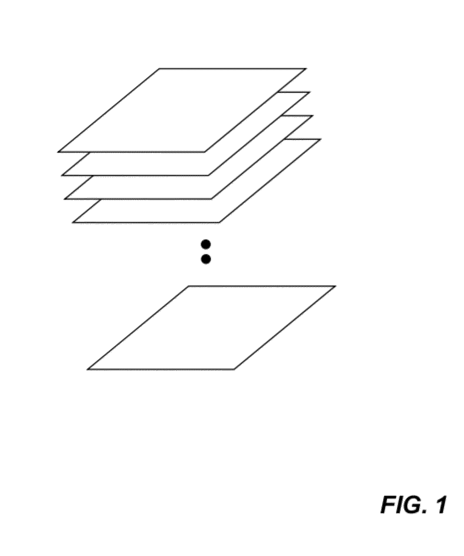
FIELD OF THE INVENTION[0001]The present invention generally relates to computer-aided engineering analysis of a structure or product having components / parts made of composite materials, more particularly to efficient data management for shell finite elements representing layered composite materials in finite element analysis.BACKGROUND OF THE INVENTION[0002]Layered composite materials have been used in many applications in engineering products from a patio to an airplane. When building an aircraft, for example, engineers need lightweight, strong material that can insulate and protect passengers while surfacing the aircraft. An aircraft made of pure metal could fail catastrophically if a small crack appeared in the skin of the airplane. On the other hand, aircraft integrating reinforced composite materials such as fiberglass, graphite, and other hybrids will be stronger and less likely to break up. Layered composite materials comprise an arbitrary number of layers or plies as shown i...

Claims


Application Information

Patent Timeline
Patent Type & Authority Patents(United States)
IPC IPC(8): G06F17/50G06F7/60G06G7/48
CPCG06F17/5018G06F17/5095G06F30/15G06F30/23
Inventor HALLQUIST, JOHN O.
Owner ANSYS
Learn More