
Distributed processing RAID system

Inactive Publication Date: 2006-07-27
CADARET PAUL
View PDF1 Cites 28 Cited by
  • Summary
  • Abstract
  • Description
  • Claims
  • Application Information

AI Technical Summary

Benefits of technology

[0022] The RAID-5 data encoding strategy employs 1 additional “parity” drive added to a RAID-set such that it provides sufficient additional data for the error correcting strategy to recover from 1 failed DSM unit within the set without a loss of data integrity. The RAID-6 data encoding strategy employs 2 additional “parity” drives added to a RAID-set such that it provides sufficient additional data for the error correcting strategy to recover from 2 failed DSM units within the set without a loss of data integrity or data availability.
[0024] The methods shown above can be extended well beyond 2 “parity” drives. Although the use of such extended RAID-methods may at first glance appear unnecessary and impractical, the need for such extended methods becomes more apparent in light of the previous discussions presented regarding large system data inaccessibility and the need for increased data-integrity and data-availability in the presence of higher component failure rates and “clustered” failures induced by the large number of components used and the fact that such components will likely be widely distributed to achieve maximum parallelism, scalability, and flexibility.
[0026] The important feature of the above table is that, in general, system MTBF figures can be greatly improved by reducing component utilization. Considering that the physics of large data storage systems in the PB / EB range generally prohibit the rapid access to vast quantities of data within such systems, it makes sense to reduce the component utilization related to data that cannot be frequently accessed. The general method described is to place such components in “stand by”, “sleep”, or “power down” modes as available when the data of such components is not in use. This reduces system power requirements and also generally conserves precious component MTBF resources. The method described is applicable to DSM units, controller units, equipment-racks, network segments, facility power zones, facility air conditioning zones, and other system components that can be effectively operated in such a manner.

Problems solved by technology

However, the basic requirement for developing effective designs that exhibit the scalability and flexibility required to implement effective PB / EB-class data storage systems is a far more challenging matter.
Such numbers of components are quite counterintuitive as compared to the everyday experience of system design engineers today and at first glance the development of such systems appears to be impractical.
Unfortunately, the scalability and flexibility of such architectures is generally quite limited as is evidenced by the data storage capacity and other attributes of high-performance data storage system architectures and product offerings commercially available today.

Method used


Image

  • Distributed processing RAID system
  • Distributed processing RAID system
  • Distributed processing RAID system

Examples


Embodiment Construction

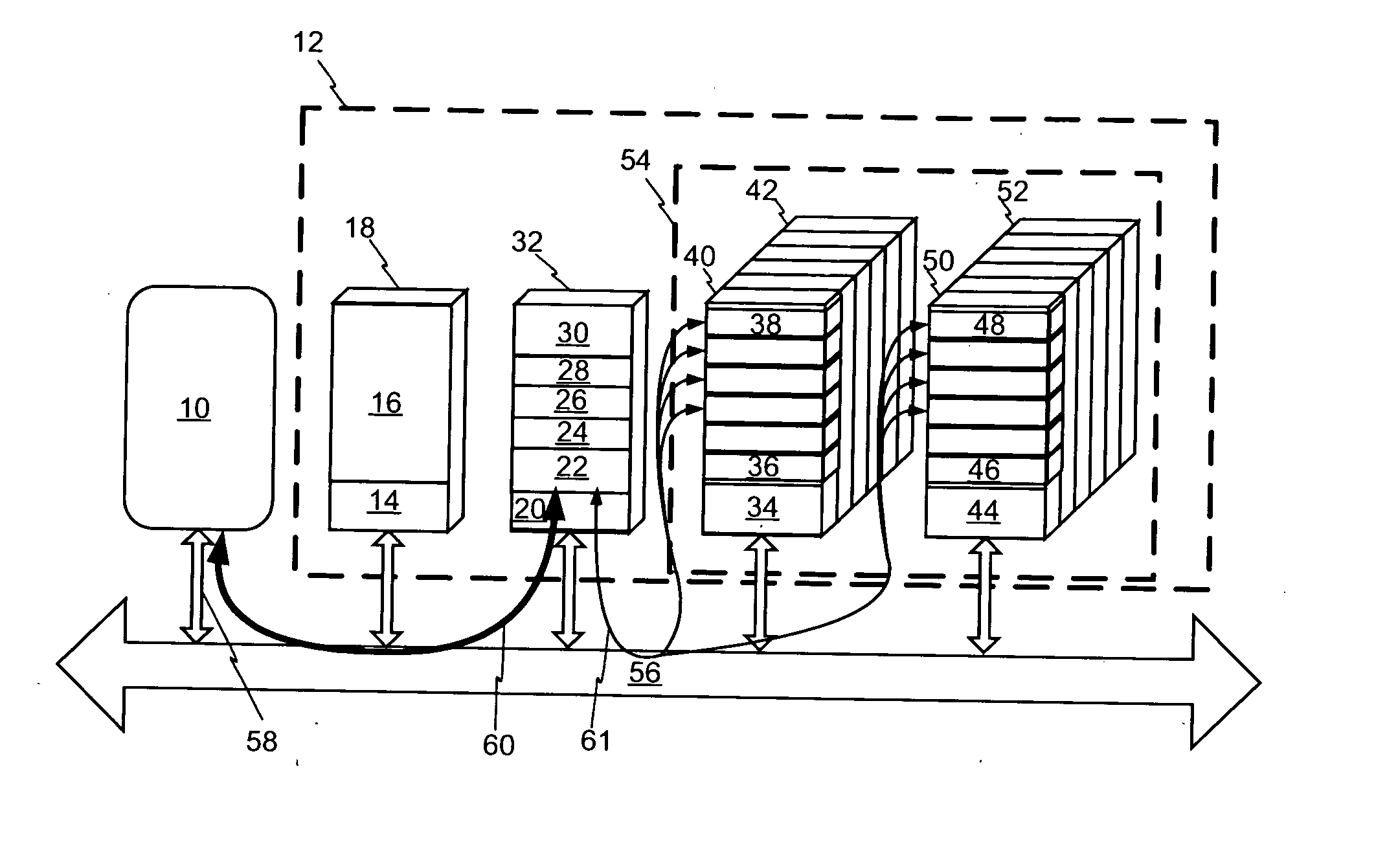
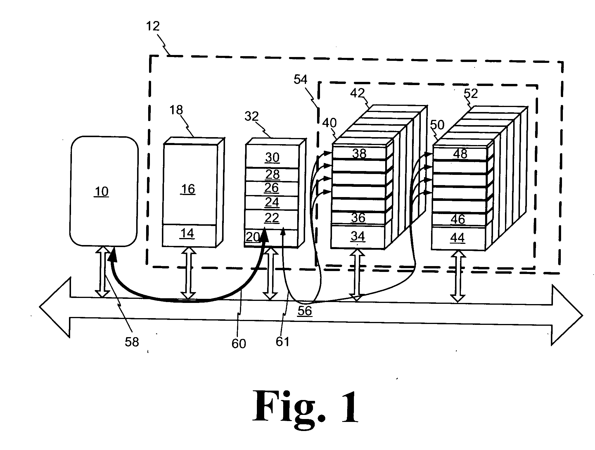
[0064] Referring to FIG. 1, a high-level block diagram of a scalable distributed processing network-centric RAID system architecture is shown. Network link 56 is any suitable extensible network communication system such as an Ethernet (ENET), Fibre-Channel (FC), or other data communication network. Network link 58 is representative of several of the links shown connecting various components to the network 56. Client computer system (CCS) 10 communicates with the various components of RAID system 12. Equipment rack 18 encloses network interface and power control equipment 14 and a meta-data management system (MDMS) components 16. Equipment rack 32 encloses network interface and power control equipment 20, several RPC units (22 through 28), and a RAID control and management system (RCS) 30. Block 54 encloses an array of data storage equipment racks shown as 40 through 42 and 50 through 52. Each data storage equipment rack is shown to contain network interface and power control equipme...


PUM


Abstract

A distributed processing RAID data storage system utilizing optimized methods of data communication between elements. In a preferred embodiment, such a data storage system will utilize efficient component utilization strategies at every level. Additionally, component interconnect bandwidth will be effectively and efficiently used; systems power will be rationed; systems component utilization will be rationed; enhance data-integrity and data-availability techniques will be employed; physical component packaging will be organized to maximize volumetric efficiency; and control logic of the implemented that maximally exploits the massively parallel nature of the component architecture.

Description

FIELD OF THE INVENTIONS [0001] The inventions described below relate to the field of large capacity digital data storage and more specifically to large capacity RAID data storage incorporating distributed processing techniques. BACKGROUND OF THE INVENTIONS [0002] Modern society increasingly depends on the ability to effectively collect, store, and access ever-increasing volumes of data. The largest data storage systems available today generally rely upon sequential-access tape technologies. Such systems can provide data storage capacities in the petabyte (PB) and exabyte (EB) range with reasonably high data-integrity, low power requirements, and at a relatively low cost. However, the ability of such systems to provide low data-access times, provide high data-throughput rates, and service large numbers of simultaneous data requests is generally quite limited. The largest disk-based data storage systems commercially available today can generally provide many tens of terabytes (TB) of ...

Claims


Application Information

Patent Timeline
IPC IPC(8): G06F12/16
CPCG06F3/0625G06F3/0626G06F3/0634G06F3/067Y02B60/1246Y02D10/00
Inventor CADARET, PAUL
Owner CADARET PAUL
Learn More