Cleaning device

a cleaning device and cloth technology, applied in carpet cleaners, carpet sweepers, cleaning machines, etc., can solve the problem of only having a small water absorption capacity of cloth, and achieve the effect of improving cleaning performance, in particular on uneven floors

Inactive Publication Date: 2013-07-30
CARL FREUDENBERG KG
View PDF25 Cites 47 Cited by
  • Summary
  • Abstract
  • Description
  • Claims
  • Application Information

AI Technical Summary

Benefits of technology

[0004]An aspect of the present invention includes developing the known cleaning device in such a way that the cleaning performance, in particular on uneven floors, is further improved.

Problems solved by technology

Furthermore, the cloth only has a small water absorption capacity because of the small volume.

Method used


Image

  • Cleaning device
  • Cleaning device
  • Cleaning device

Examples


Embodiment Construction

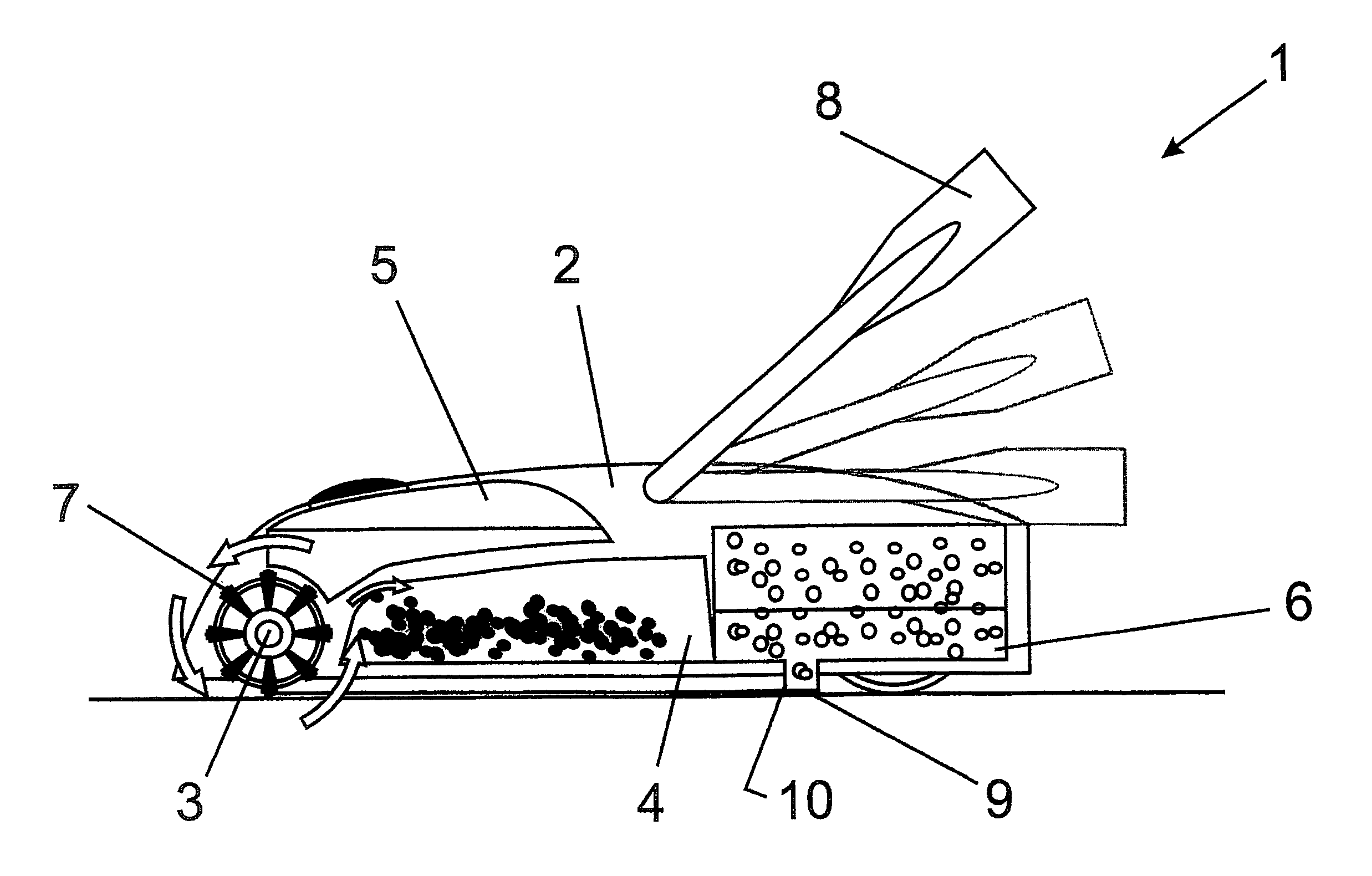
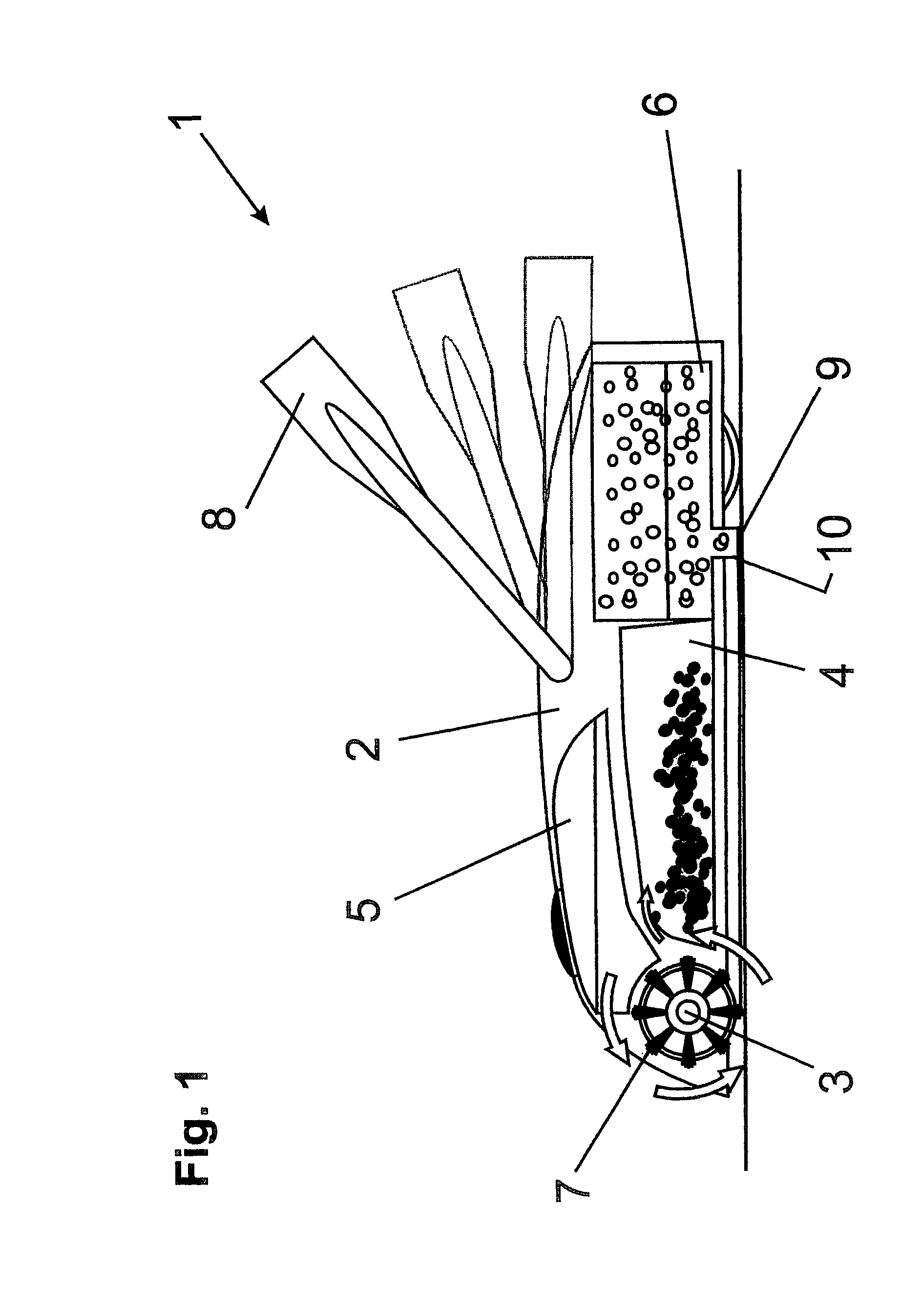
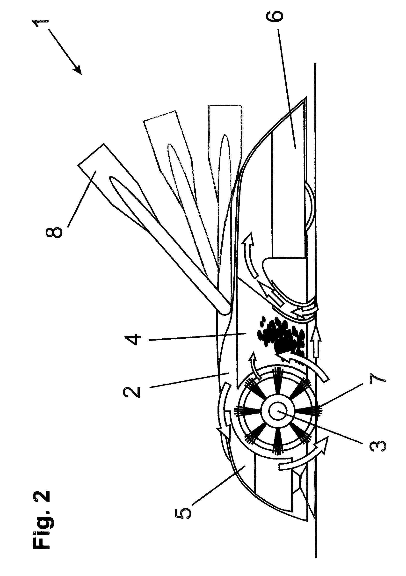
[0029]FIG. 1 shows a cleaning device 1, consisting of a base body 2, on which a handle 8 is fastened by means of an articulated joint. A motor-driven rotatable roller brush 3, by means of which dirt is conveyed into the dirt container 4 arranged behind the roller brush 3, is arranged in the front part of the base body 2. The roller brush 3 is driven by a battery-operated electric motor, lithium-ion batteries preferably being used as the batteries. Furthermore, the base body 2 contains a liquid container 5 to receive cleaning liquid. The liquid container 5 is arranged in such a way that the cleaning liquid can be applied directly to the roller brush 3. For this purpose, a pump may also be connected between the liquid container 5 and roller brush 3 which increases the liquid pressure and thus improves the cleaning action. In other configurations, the liquid container may also be arranged in the handle 8. A mechanism 6 to receive soiled cleaning liquid is located behind the roller brus...


PUM


Abstract

A cleaning device for cleaning a floor includes a base body, a rotatable roller brush disposed on the base body, a dirt container disposed on the base body, a liquid container configured to receive a cleaning liquid disposed on the base body; and a sponge configured to receive a soiled cleaning liquid disposed on the base body.

Description

CROSS REFERENCE TO PRIOR APPLICATIONS[0001]This application is a U.S. National Phase application under 35 U.S.C. §371 of International Application No. PCT / EP2008 / 010749, filed Dec. 17, 2008, which claims priority to German Application No. DE 10 2007 061 607.6, filed Dec. 18, 2007. The International Application was published in German on Jun. 25, 2009 as WO 2009077169 under PCT Article 21 (2).FIELD[0002]The invention relates to a cleaning device, comprising a base body, on which a rotatable roller brush, a dirt container, a liquid container for receiving cleaning liquid and a mechanism for receiving soiled cleaning liquid are arranged.BACKGROUND[0003]A cleaning device of this type is known from WO 2005 / 087075. The previously known cleaning device consists of a base body, on which a rotatable roller brush which is driven by an electric motor is fastened, said brush transporting the collected dirt into a dirt container arranged behind the roller brush. Coarse dirt is received by the ro...

Claims


Application Information

Patent Timeline
Patent Type & Authority Patents(United States)
IPC IPC(8): A47L11/00
CPCA47L11/22A47L11/33A47L11/4016A47L11/4036A47L11/4075A47L11/4083
Inventor DINGERT, UWE
Owner CARL FREUDENBERG KG
Why Eureka
Try Eureka