Clip

a clip and clip technology, applied in the field of clips, can solve the problems of complex structure of the base, backlash may arise, complicated clip structure, etc., and achieve the effect of simple formation

Inactive Publication Date: 2013-07-30
PIOLAX CO LTD
View PDF20 Cites 28 Cited by
  • Summary
  • Abstract
  • Description
  • Claims
  • Application Information

AI Technical Summary

Benefits of technology

[0023]As described above, since the plate spring member includes a leg portion bent in a V-shape to hold the shaft portion of the pin member, the plate spring member is retained with the pin member. And, it is not necessary to provide a plate spring member fitting-in slit at the pin member (synthetic resin base) as in JP-3120355-B or provide a pin member inserting through-hole at the plate spring member (clip) as in JP-3120356-B, and the pin member and the plate spring member can be made relatively simple in structure.
[0024]Further, the abutting portions provided between the distal ends of the inclined portions of the V-shaped leg portion and the flange portions abut against the diameter-expanded portion of the shaft portion to expand the V-shaped leg portion. Since the engagement portions extending from the distal ends of the inclined portions are sufficiently expanded, even when a thickness of the mounting subject having the mounting hole is thin, the clip with can be tightly fixed with the mounting hole without backlash regardless of the thickness.

Problems solved by technology

In the clip of JP-3120355-B, a slit is required at the shaft portion and enlarged head portion of the base in order to assemble the spring body with the base, and thus, the structure of the base is complicated.
As a result, since an expanding amount at the stopper portion side of the spring body is insufficient, it is not suitably applicable to the mount-base member having thin plate thickness, and backlash may arise in some cases.
Further, since the spring portion engaged with the back side of the mounting hole is formed by folding back each side of the clip outside, the structure of the clip is complicated, and there is a problem in terms of productivity.

Method used


Image

  • Clip
  • Clip
  • Clip

Examples


Embodiment Construction

[0032]Hereinafter, embodiments of the present invention will be described with reference to FIGS. 1 to 5B.

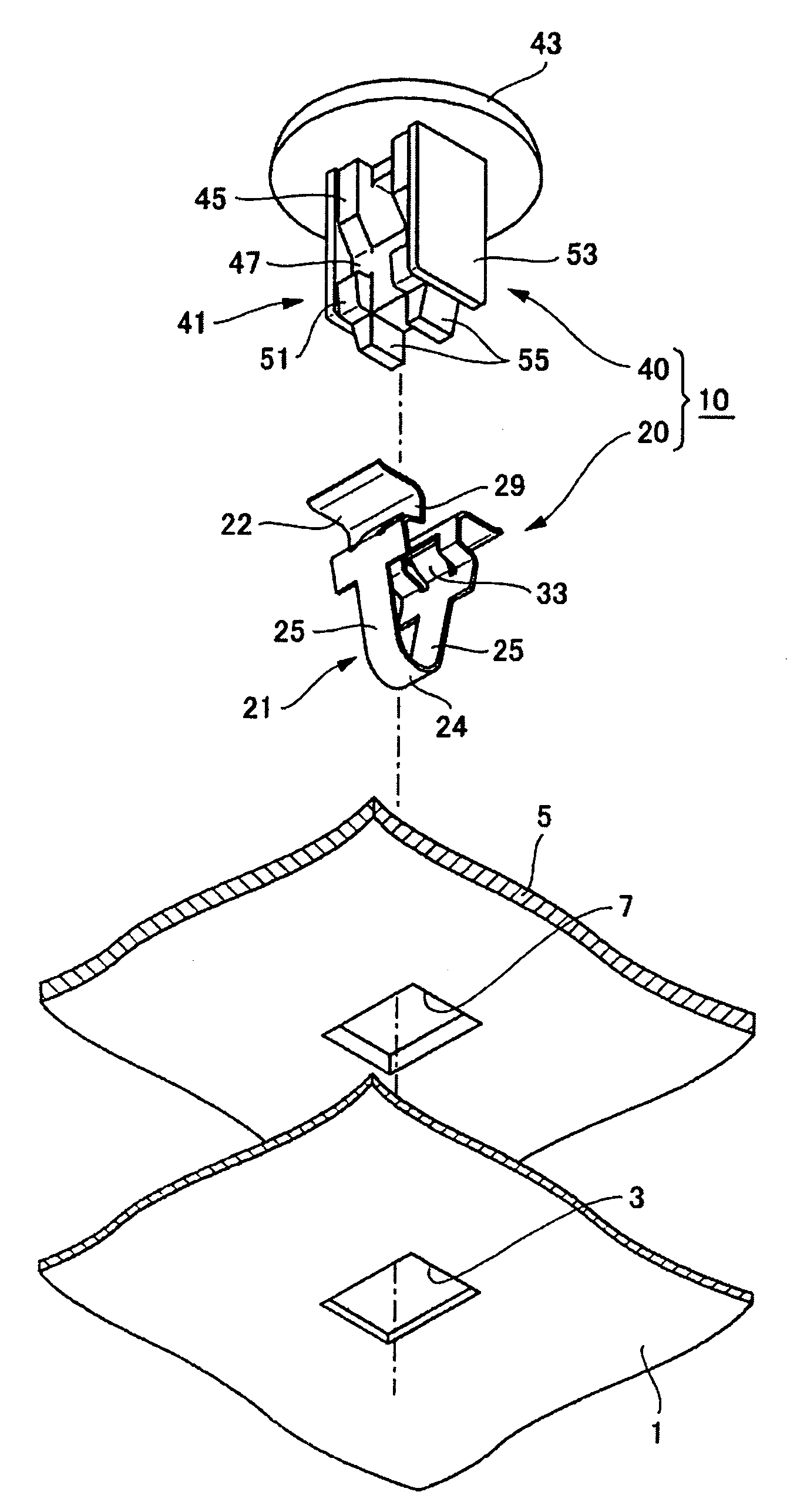
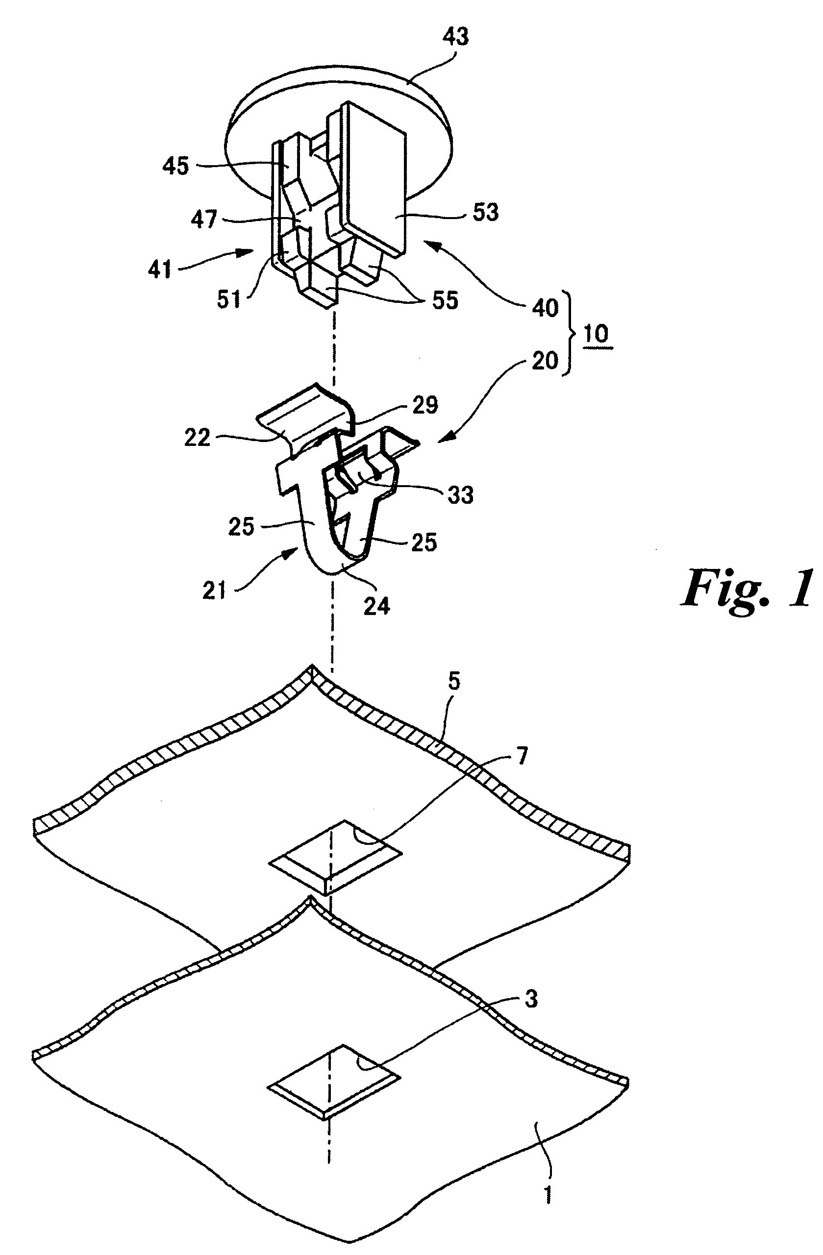
[0033]As shown in FIG. 5B, for example, a clip 10 according to an embodiment is inserted into and fixed with a mounting hole 3 formed in a mount-base member 1 such as a body panel. For example, a mounting-subject member 5 such as a trim board, a panel member, a garnish, a cover, an assist grip is mounted to the mount-base member 1 through the clip 10.

[0034]As shown in FIG. 1, the clip 10 includes a plate spring member 20 and a pin member 40 assembled with the plate spring member 20.

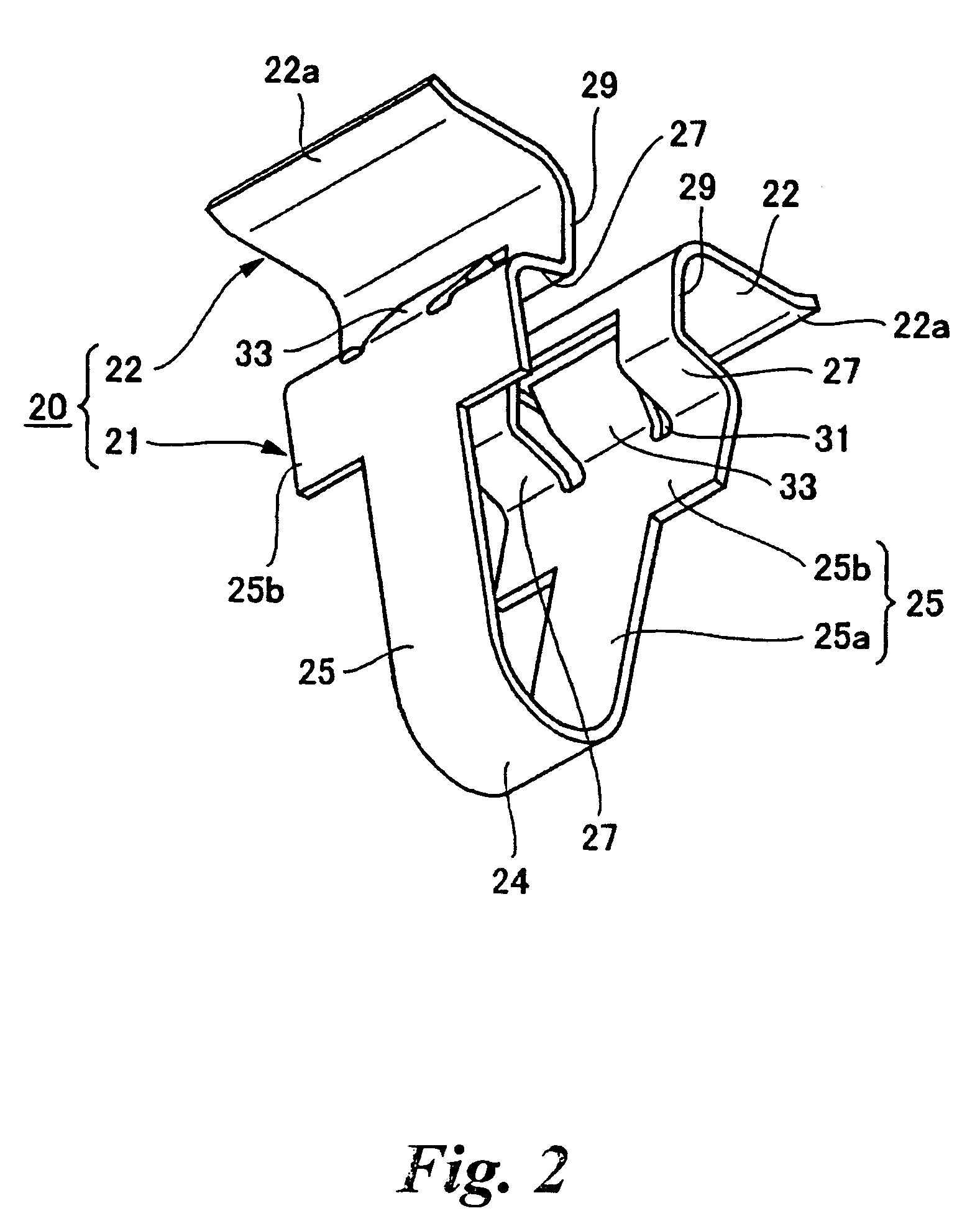
[0035]First, the plate spring member 20 will be described with reference to FIG. 2 and FIGS. 4A and 4B. The plate spring member 20 is formed from a metal plate. The plate spring member 20 includes a leg portion 21 and flange portions 22. The leg portion 21 is bent into a V-shape so as to sandwich the shaft portion of the pin member 40 as described later, and the flange portions 22 outwardly extend fro...


PUM


Abstract

According to embodiments of the present invention, a clip includes: a plate spring member having a leg portion and flange portions; a pin member having a shaft portion and a head portion. The leg portion has: inclined portions outwardly extending from a bent portion; engagement portions inwardly extending from the inclined portions; and abutting portions connected between the inclined portions and the flange portions. The shaft portion has: a proximal-side diameter-expanded portion; and a distal-side diameter-reduced portion. When the plate spring member is assembled with the pin member and flange portions abut a front side circumference of the mounting hole, the diameter-expanded portion abut the abutting portions to expand the leg portion through a further pushing operation of the pin member thereby engaging the engagement portions with a back side circumference of the mounting hole.

Description

CROSS-REFERENCE TO RELATED APPLICATION(S)[0001]This application claims priority from Japanese Patent Application No. 2009-130612 filed on May 29, 2009, the entire contents of which are incorporated herein by reference.BACKGROUND[0002]1. Field of the Invention[0003]An aspect of the present invention relates to a clip, for example, inserted into a mounting hole formed in a body panel of a vehicle for fixing.[0004]2. Description of the Related Art[0005]A clip is used to mount a mounting-subject member such as a trim board to a mount-base member such as a body panel of a vehicle, for example.[0006]JP-3120355-B discloses a clip composed of a synthetic resin base (hereinafter, referred to as a “base”) and a metal spring body (hereinafter, referred to as a “spring body”). The base includes an enlarged head portion and a shaft portion, defines a slit extending from the enlarged head portion to inside the shaft portion and fitted in by the spring body, and is provided with a guide wall havin...

Claims


Application Information

Patent Timeline
Patent Type & Authority Patents(United States)
IPC IPC(8): F16B13/04
CPCF16B5/0642F16B21/075Y10T403/54
Inventor AOKI, RYOUARISAKA, OOMI
Owner PIOLAX CO LTD
Why Eureka
Try Eureka