
Laterally restrained joint structure

a joint structure and lateral restraint technology, applied in the field of joint structure, can solve the problems of complex stress distribution, affecting the axial stiffness and and buildings will induce lateral loads, and achieve the effect of enhancing the buckling strength of the gusset pla

Inactive Publication Date: 2013-08-13
NAT TAIWAN UNIV OF SCI & TECH
View PDF9 Cites 18 Cited by
  • Summary
  • Abstract
  • Description
  • Claims
  • Application Information

AI Technical Summary

Benefits of technology

The invention provides a joint structure that includes a restraining member to prevent unexpected deformation of a gusset plate or two-force member. This enhances the buckling strength of the gusset plate, reinforces buildings, and ensures safety and reliability. The restraining member is installed on the gusset plate to provide lateral bracing and is determined by the buckling modes of the gusset plate. Overall, the invention improves the stability and strength of the joint structure.

Problems solved by technology

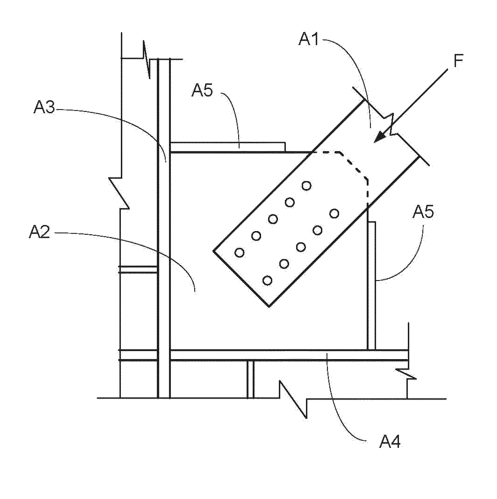
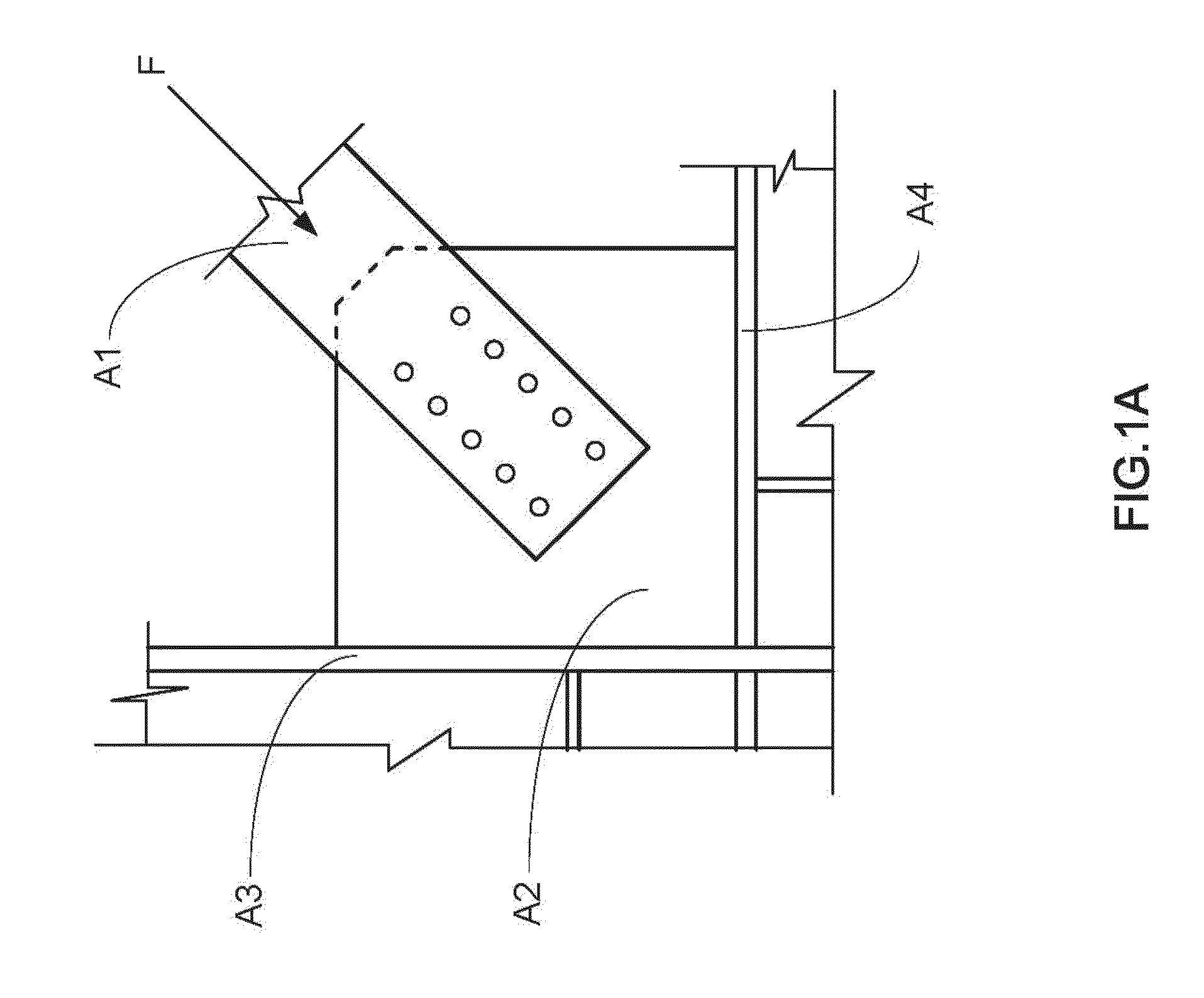
With the effect of complex geometric shape, the distribution of the stress is complicated.
When an earthquake occurs, the buildings will induce a lateral load caused by ground motion.
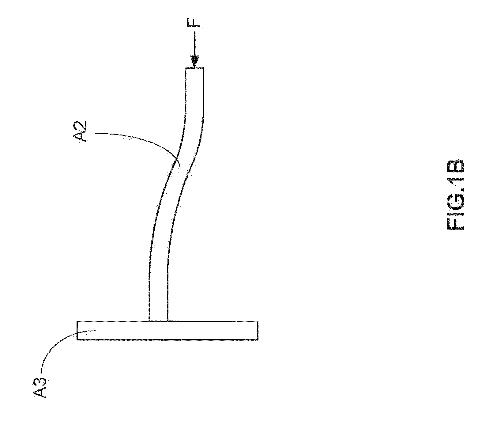
However, when the gusset plate A2 bears a larger compression, lateral deformation and buckling will occur to affect the axial stiffness and strength of the gusset.

Method used


Image

  • Laterally restrained joint structure
  • Laterally restrained joint structure
  • Laterally restrained joint structure

Examples


Embodiment Construction

[0031]The technical contents and characteristics of the present invention will be apparent with the detailed description of a preferred embodiment accompanied with related drawings as follows. It is noteworthy that the drawings are provided for the purpose of illustrating the present invention, but not intended for limiting the scope of the invention.

[0032]With reference to FIGS. 2A and 2B for schematic views of a joint structure in accordance with the first preferred embodiment of the present invention, the joint structure is a laterally restrained joint structure used in a structure, and the laterally restrained joint structure comprises: a structural member 11 for an architectural structure; a gusset plate 21, having at least one side 211, and connected to the structural member 11, and a two-force member 12 jointed to the gusset plate 21 with respect to the structural member 11; and a restraining member 31, installed over the side 211 of the gusset plate 21, and connected to the ...


PUM


Abstract

A laterally restrained joint structure including a structural member, a gusset plate and at least one restraining member is disclosed. The gusset plate is connected to the structural member, and a two-force member is disposed opposite to the structural member and connected to the gusset plate. The restraining member is disposed over side or at edges of the gusset plate and connected to the structure member, so that the lateral deformation of the gusset plate can be controlled and the buckling strength of the gusset plate can be enhanced by the restraining member, and the laterally restrained joint structure is capable of reinforcing a building.

Description

BACKGROUND OF THE INVENTION[0001]1. Field of the Invention[0002]The present invention relates to a joint structure capable of reinforcing bridges and buildings, and more particularly to the joint structure with at least one restraining member capable of enhancing the buckling strength of steel plates, and the joint structure is installed on a side of a gusset plate (or a joint plate) of a truss or a diagonal brace to prevent buckling caused by lateral deformations of the gusset plate.[0003]2. Description of Related Art[0004]Gusset plate (also known as joint plate) is generally installed between a chord member, a beam member and a column member and connected to a truss web member or a two-force member to transmit loads, and thus the gusset plate can be applied in bridges and buildings. In general, most gusset plates are made of steel plates, and the steel plates are galvanized or coated to protect the gusset plate from being rusted, so that most galvanized steel plates can be used ou...

Claims


Application Information

Patent Timeline
Patent Type & Authority Patents(United States)
IPC IPC(8): E04B1/38E04C5/00E04B1/98
CPCE04H9/02E01D22/00E04H9/028E04H9/0237
Inventor CHANG, CHING-CHANGCHEN, SHENG-JIN
Owner NAT TAIWAN UNIV OF SCI & TECH
Learn More