
Cable protection and guide device

a guide device and cable protection technology, applied in the direction of cable arrangement between relatively moving parts, machine supports, manufacturing tools, etc., can solve the problems of large amount of abrasion, high impact noise, and insufficient strength of link side plates against crush forces, so as to improve the accuracy of linear position, improve the integrity of link frame bodies, and facilitate the effect of accurately defining relative positions

Active Publication Date: 2013-08-13
TSUBAKIMOTO CHAIN CO
View PDF10 Cites 19 Cited by
  • Summary
  • Abstract
  • Description
  • Claims
  • Application Information

AI Technical Summary

Benefits of technology

The cable protection and guide device described in this patent addresses several problems in the prior art. It can correct the position of link frame bodies, prevent twisting, increase strength against crush forces, and reduce abrasion and impact noise. Additionally, when the device moves from linear to flexional position, the load is dispersed into contact portions of flexional position restricting surfaces, reducing the load on the plate structure of the linkage portion.

Problems solved by technology

The aforementioned conventional cable protection and guide device 500 has a problem that mutually adjacent link frame bodies may be twisted with respect to each other by external force when the device 500 moves to the linear position, a problem that the link frame bodies may be twisted with respect to each other by external force when the device 500 is in the linear position, a problem that the strength (or durability) of the link side plate against crush forces is not sufficient since a load that acts on contacting portions does not disperse when the device 500 moves to the linear position, and a problem that a large amount of abrasion and loud impact noise occurs when the device 500 moves to the linear position.

Method used


Image

  • Cable protection and guide device
  • Cable protection and guide device
  • Cable protection and guide device

Examples


embodiments

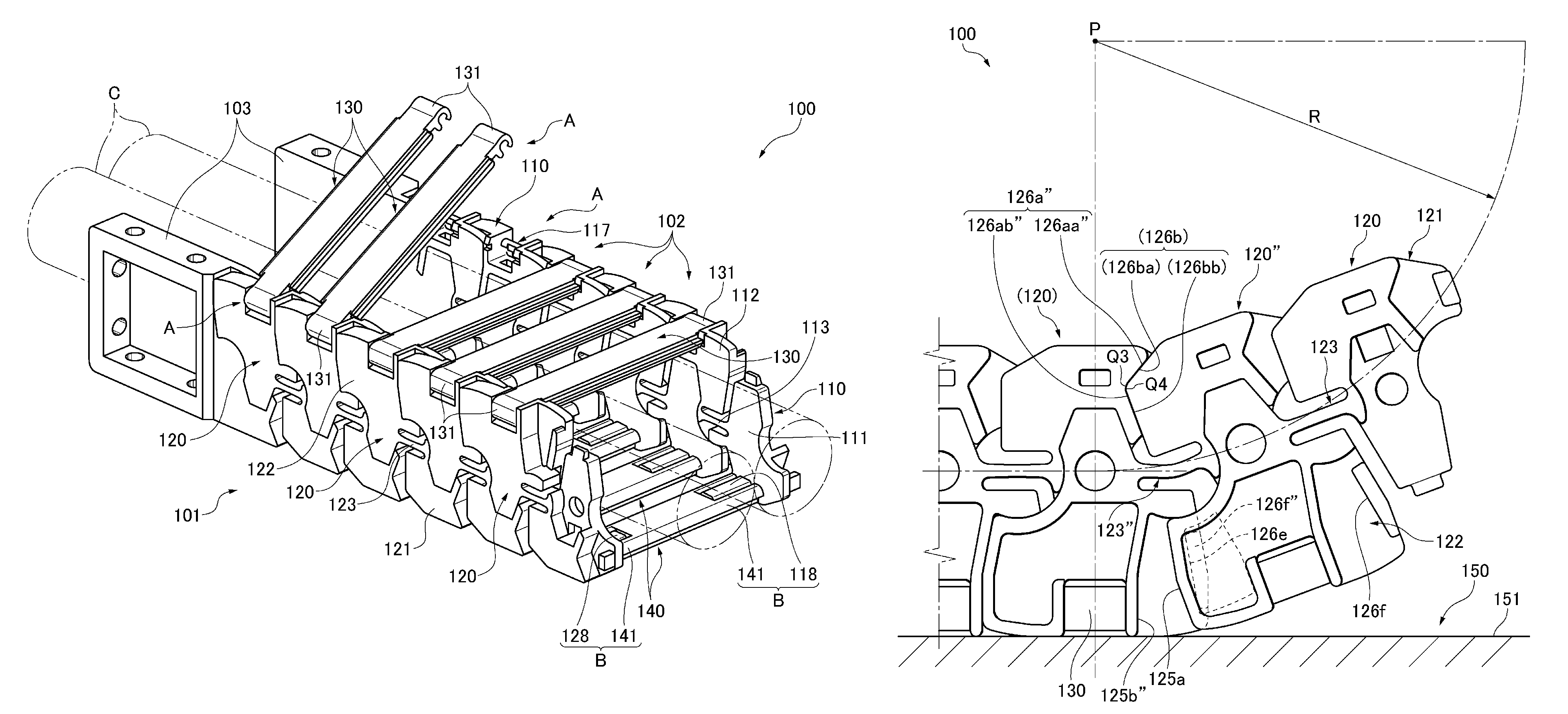
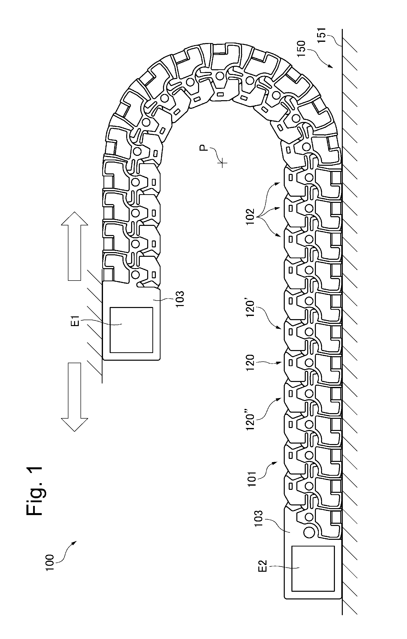
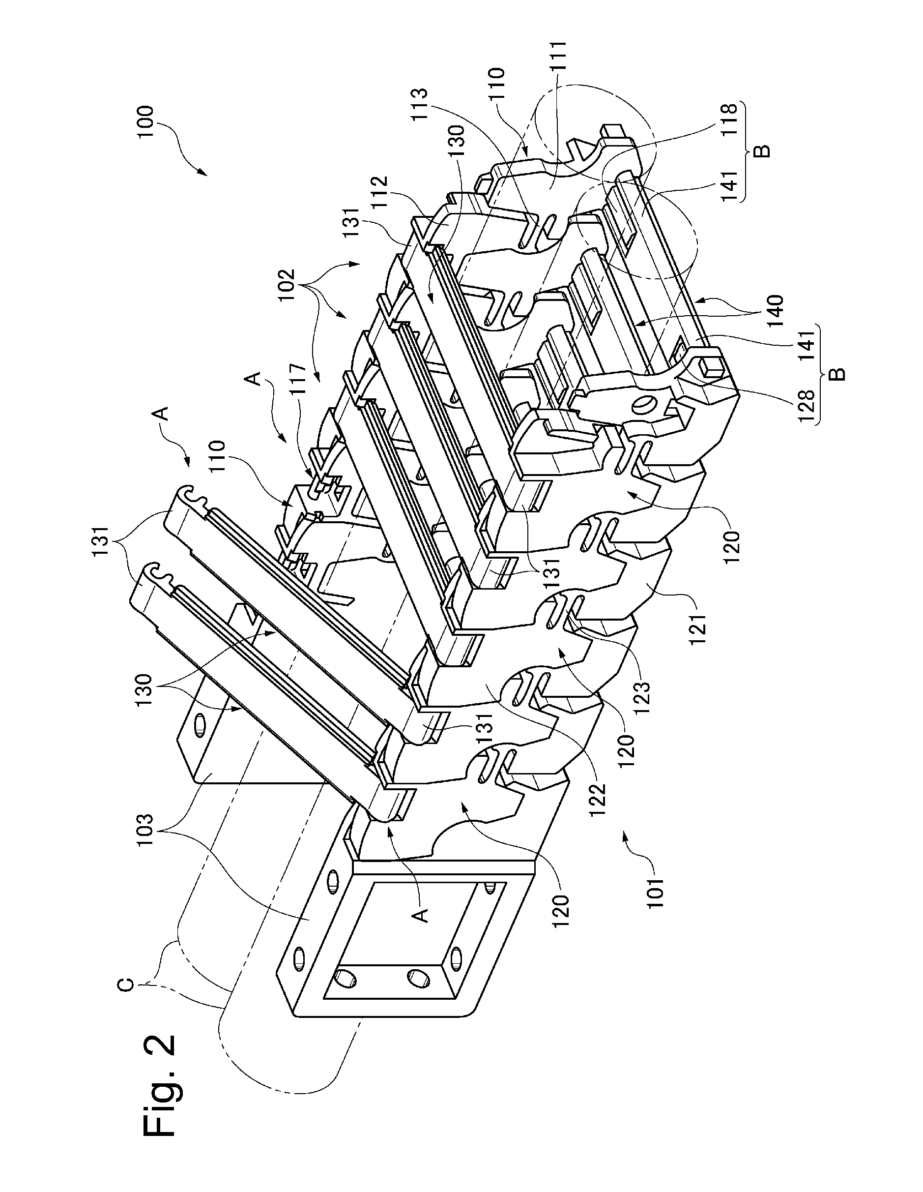
[0054]A cable protection and guide device 100 of one embodiment of the present invention will now be described on the basis of FIGS. 1 to 7.

[0055]FIG. 1 is a schematic front view of the cable protection and guide device 100 of one embodiment of the present invention. FIG. 2 is a perspective view of the cable protection and guide device 100 of one embodiment of the present invention. FIG. 3 is a perspective view of a second link side plate 120 in one embodiment of the present invention viewed from an outer side. FIG. 4 is a perspective view of the second link side plate 120 in one embodiment of the present invention viewed from an inner side. FIG. 5 is a diagram showing the cable protection and guide device 100 of one embodiment of the present invention in a linear position. FIG. 6 is a diagram showing the cable protection and guide device 100 of one embodiment of the present invention at the beginning of flexing. FIG. 7 is a diagram showing the cable protection and guide device 100 ...


PUM


Abstract

A device capable of correcting the relatively twisted positional relationship of mutually adjacent link frame bodies, and precisely place the link frame bodies at appropriate positions. A link side plate includes a rear side plate portion having first and second linear position holding surfaces respectively at rear and front sides thereof in a longitudinal direction. The first linear position holding surface has a convex shape formed with two faces whose attitudes are mutually different with respect to a lateral direction. The second linear position holding surface has a concave shape formed with two faces whose attitudes are mutually different with respect to the lateral direction.

Description

CROSS REFERENCE TO RELATED APPLICATIONS[0001]The disclosure of Japanese Patent Application No. 2012-040566 filed on Feb. 27, 2012, and on which this application claims priority, is herein incorporated by reference in its entirety.FIELD OF THE INVENTION[0002]The present invention relates to a cable protection and guide device which securely protects and guides a flexible cable, such as an electric cable for transmitting electric signals or supplying electricity or a hose for supplying oil or air pressure, that connects a movable portion and a fixed portion of an industrial machine or a vehicle.BACKGROUND ART[0003]In the prior art, there is known a cable protection and guide device including a number of link frame bodies connected to each other in a longitudinal direction of a cable (referred to as “a cable longitudinal direction” hereinafter). Each of the link frame bodies has a pair of link side plates provided so as to be spaced from each other in a lateral direction, and connectin...

Claims


Application Information

Patent Timeline
IPC IPC(8): F16G13/16F16G3/04
CPCF16G13/16H02G11/006H02G11/00B25J19/00
Inventor KOMIYA, SHOICHIRO
Owner TSUBAKIMOTO CHAIN CO
Learn More