Device for diluting viscous substance
a technology of viscous substance and diluting device, which is applied in the direction of rotary stirring mixer, transportation and packaging, lighting and heating apparatus, etc., can solve the problems of insufficient dilution efficiency and limit in absorbing water vapor, and achieve high viscosity, efficient dilution, and increase the surface area of viscous substance
- Summary
- Abstract
- Description
- Claims
- Application Information
AI Technical Summary
Benefits of technology
Problems solved by technology
Method used
Image
Examples
first embodiment
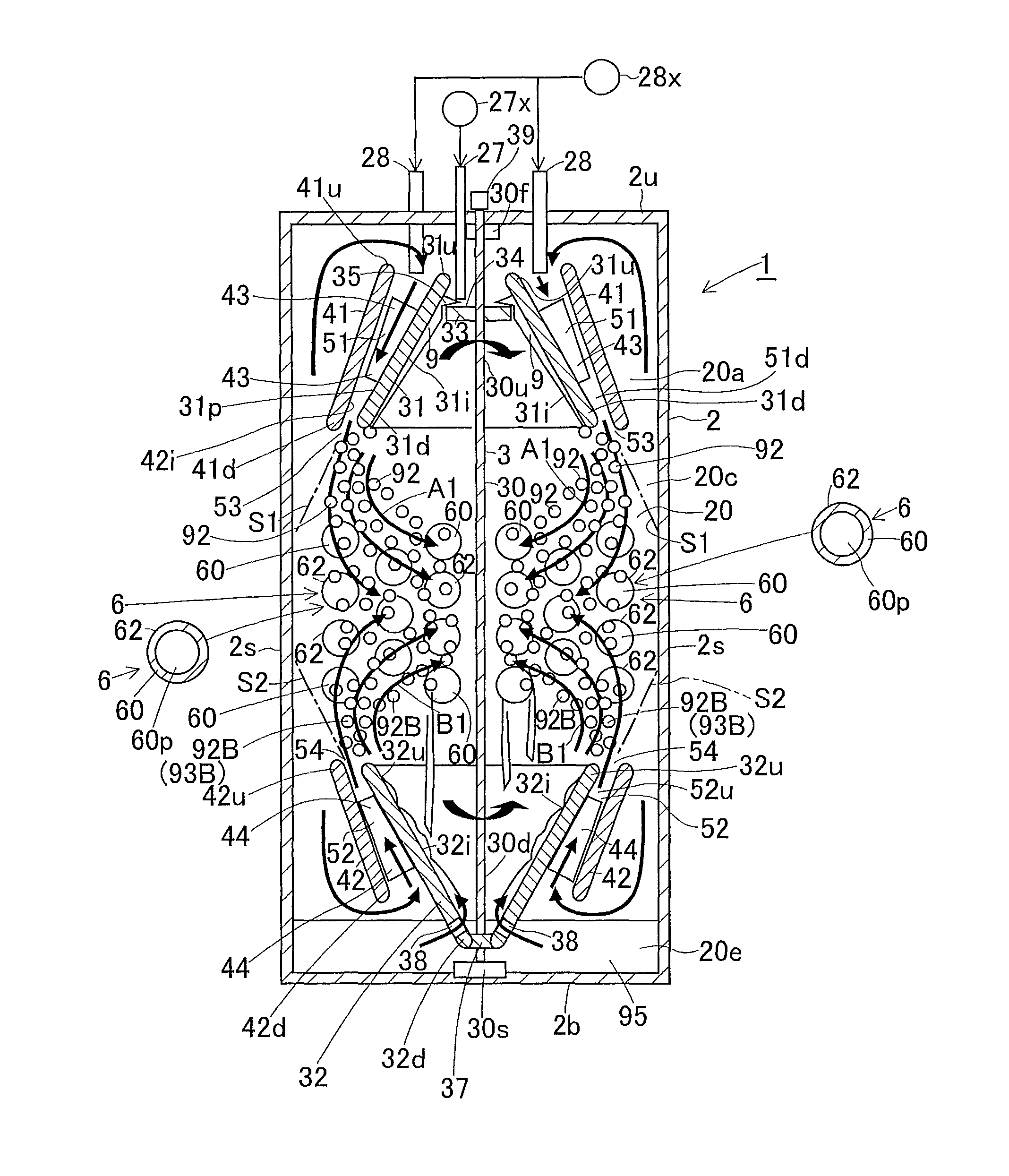
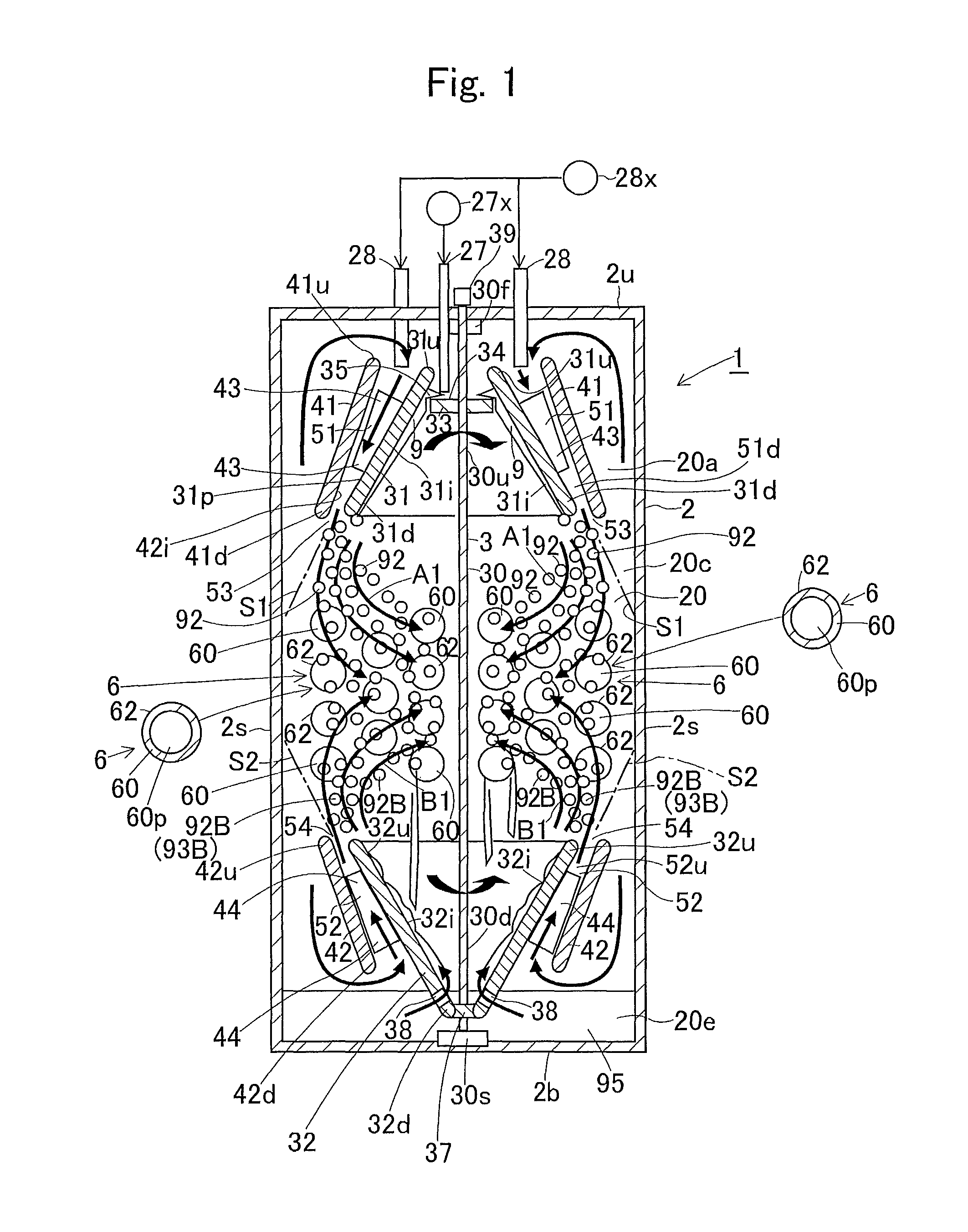
[0029]Hereinafter, a first embodiment of the present invention will be described with reference to FIG. 1. The present embodiment is applied to an absorber 1 in an absorption heat pump device (an absorption refrigerator). As shown in FIG. 1, the absorber 1 comprises a vessel 2 having a dilution chamber 20, an absorbing liquid supply portion 27 provided in the vessel 2 and serving as a viscous substance supply portion, a rotor 3 rotatably provided in the dilution chamber 20 of the vessel 2, and a water vapor supply portion 28 provided in the vessel 2 and serving as a diluent supply portion. The vessel 2 comprises an upper wall 2u, a bottom wall 2b, and a side wall 2s. The dilution chamber 20 comprises a machine chamber 20a on an upper side, a heat exchange chamber 20c provided under the machine chamber 20a, and a reservoir chamber 20e provided under the heat change chamber 20c.
[0030]The absorbing liquid supply portion 27 serving as a viscous substance supply portion is provided on t...
second embodiment
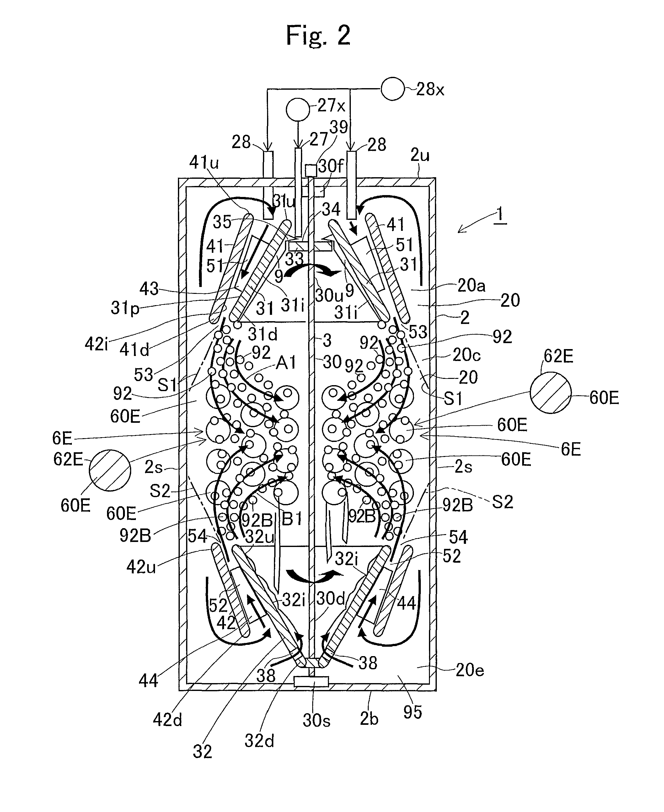
[0057]FIG. 2 shows a second embodiment. The present embodiment has basically similar constitution and effects to those of the first embodiment. However, a member for attachment 6E comprising a plurality of bars 60E having a circular cross section is provided instead of the heat transfer pipes 60. The member for attachment 6E does not have a function to flow a refrigerant. The bars 60E may have a rectangular or triangular cross section.
[0058]The fine particle group 93 of the fine particles 92 formed by the first rotor 31 head for the member for attachment 6E and get attached to outer surfaces 62E of the bars 60E. The fine particles 92 of the highly viscous absorbing liquid 9 attached to the member for attachment 6E are contacted with and absorb water vapor in the dilution chamber 20 and get diluted. Upon absorbing water vapor, the highly viscous absorbing liquid 9 having viscosity decreases in viscosity, and accordingly drops down from the outer surfaces 62E of the bars 60E toward th...
third embodiment
[0061]FIG. 3 shows a third embodiment. The present embodiment has basically similar constitution and effects to those of the first embodiment. An absorber 1 comprises a vessel 2 having a dilution chamber 20, an absorbing liquid supply portion 27 provided in the vessel 2 and serving as a viscous substance supply portion, a rotor 3H rotatably provided in the dilution chamber 20 of the vessel 2 and constituting a rotary atomizer, and a water vapor supply portion 28 provided in the vessel 2 and serving as a diluent supply portion. The vessel 2 comprises an upper wall 2u, a bottom wall 2b, and a side wall 2s. The dilution chamber 20 has a reservoir chamber 20e on a lower side thereof.
[0062]The absorbing liquid supply portion 27 is provided on the upper wall 2u of the vessel 2 and supplies a highly viscous absorbing liquid 9 (a viscous substance) fed from a supply source 27x downward to the dilution chamber 20. The water vapor supply portion 28 is provided on the upper wall 2u of the vess...
PUM
| Property | Measurement | Unit |
|---|---|---|
| sizes | aaaaa | aaaaa |
| sizes | aaaaa | aaaaa |
| sizes | aaaaa | aaaaa |
Abstract
Description
Claims
Application Information
 - R&D
- Intellectual Property
- Life Sciences
- Materials
- Tech Scout
- Unparalleled Data Quality
- Higher Quality Content
- 60% Fewer Hallucinations
Browse by: Latest US Patents, China's latest patents, Technical Efficacy Thesaurus, Application Domain, Technology Topic, Popular Technical Reports.
© 2025 PatSnap. All rights reserved.Legal|Privacy policy|Modern Slavery Act Transparency Statement|Sitemap|About US| Contact US: help@patsnap.com


