Trimmer head spool for use in flexible line rotary trimmer heads having improved line loading mechanism

a technology of rotary trimmer head and spool, which is applied in the direction of metal working apparatus, agriculture tools and machines, and time-consuming tasks for professional users, can solve the problems of not being able to remove the spool, the difficulty of properly loading the line on the spool is the most common, and the need to lock the spool, so as to minimize material usage and concentration, improve the spool product, and easy to lock. and releasably lock

Active Publication Date: 2013-08-20
PROULX MFG
View PDF7 Cites 24 Cited by
  • Summary
  • Abstract
  • Description
  • Claims
  • Application Information

AI Technical Summary

Benefits of technology

[0010]Briefly, the present invention comprises an improved spool construction for a rotary trimmer head configured to facilitate loading of new cutting line onto the trimmer head spool and the removal of worn or broken line from the spool for replacement, both without having to interrupt the operative connection between the spool and the housing. To provide such loading and unloading of the line, the trimmer head spool is operatively connected to the trimmer head housing for rotation therewith about a common axis and includes a cylindrical body portion, at least one flange projecting radially therefrom so as to define at least one cutting line storage area about the body portion of the spool adjacent the flange and a line receptor channel that traverses the spool. The line receptor channel has geometrically opposed open ends located in a spool flange that are radially alignable with the line openings in the housing upon relative rotation of the spool and the housing. The channel preferably extends radially inwardly from the opposed open ends thereof, downwardly along opposed portions of the body portion of the spool and transversely of the body portion proximate the lowermost surface of the spool where the channel defines an open portion so as to provide access to the channel while the spool remains operatively connected to the housing. This configuration allows a length of cutting line to be inserted through the line receptor channel and the aligned openings in the housing skirt and wrapped about the spool without having to interrupt the operative connection between the spool and the housing, and in the event of a line breakage proximate a line opening in the housing skirt, a user can grip in the open portion of the channel and pull on the line in a direction away from the spool and generally parallel to the axis of rotation, whereby the cutting line and the spool can be pulled from the head for replacement without having to interrupt the operative connection between the spool and the housing.
[0011]To facilitate the fabrication of the above described line receptor channel in the spool so as to provide the channel with a continuously smooth interior wall surface while reducing the weight of the spool and concentrations of material, the spool of the present invention is molded in two separate sections that can be readily locked together to form the trimmer head spool. The upper spool section includes the spool flange in which the outer line receptor channel openings are formed and through which the inwardly extending opposed radial channel portions extend. The opposed radial channel portions terminate at their inner ends in opposed openings on opposite sides of a large centrally disposed cavity in the upper portion of the spool. A pair of depending vertical walls extend across the cavity in parallel alignment with the outer edges of the opposed inner channel openings and a pair of guide surfaces extend inwardly and downwardly between the two depending vertical walls along opposed curvilinear paths from the inner channel openings and terminate in radially spaced substantially vertical orientations. The resulting configuration defines a pair of opposed outer hollow cavities separated by the two depending parallel walls and a pair of radially spaced and extending opposed inner cavities disposed between the depending walls and bordered along their respective upper and inner ends by the curvilinear guide surfaces.
[0014]The guide members on the lower spool section preferably each extend upwardly from the lower spool surface without additional lateral support so as to allow the guide members to flex slightly in a radial direction such that the outer upper end surfaces of the guide members can be provided with outwardly projecting locking elements adapted to be received within opposed apertures formed in the upper spool section below the inner channel openings therein upon the upper and lower spool sections being pressed together whereby the upper section of the spool can be readily and releasably locked to the lower spool section.
[0015]The above-described spool construction not only allows for a smooth interior channel surface, it also minimizes material usage and concentrations to provide an improved spool product.

Problems solved by technology

Difficulty in properly loading the line on the spool is the most common complaint of home users of flexible line trimmers.
It also is a time consuming task for the professional user.
While those configurations do facilitate the loading of line onto the spool, they did not eliminate the need to remove the spool from the housing (known in the trade as splitting the head) in the event the cutting line breaks proximate the eyelet during use.
Unfortunately, this is a frequent occurrence when the rapidly rotating line strikes a solid object such as a fence post.
While the trimmer head that is the subject of U.S. Pat. No. 7,797,839 has greatly simplified line loading and replacement for the user, the line receptor channel in the trimmer head that traverses the spool requires a relatively complicated molding process and the exercise of substantial care during fabrication to provide a smooth continuous interior channel surface along the curvilinear portions thereof.
The existing spools in which that channel is formed also are relatively heavy due to the amount of material employed in their fabrication and are subject to warpage and surface irregularities as a result of shrinkage during the cooling of the freshly molded spools due to large concentrations of material.

Method used


Image

  • Trimmer head spool for use in flexible line rotary trimmer heads having improved line loading mechanism
  • Trimmer head spool for use in flexible line rotary trimmer heads having improved line loading mechanism
  • Trimmer head spool for use in flexible line rotary trimmer heads having improved line loading mechanism

Examples


Embodiment Construction

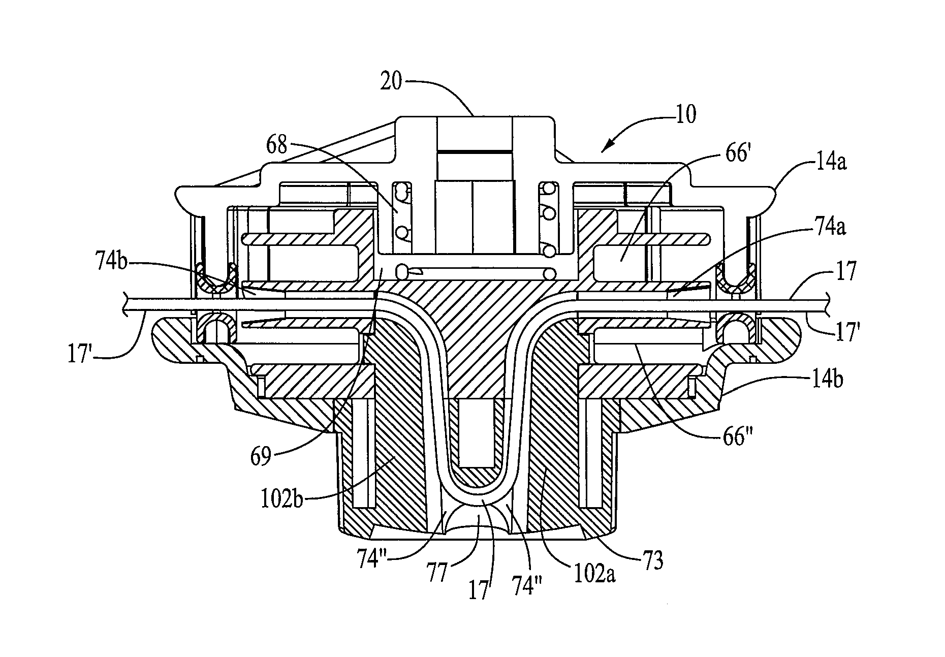
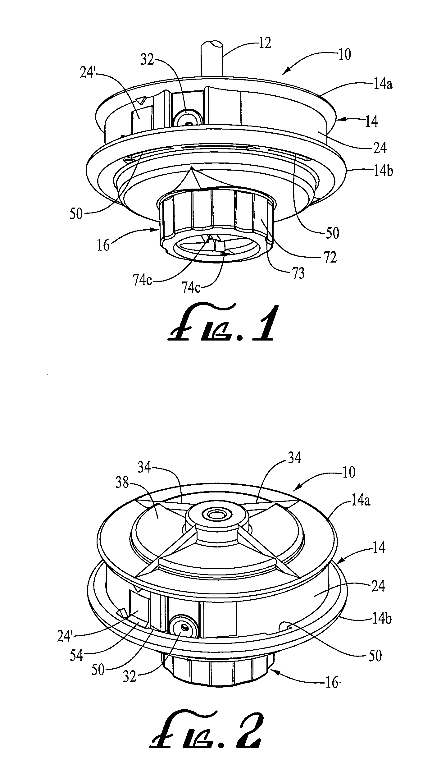
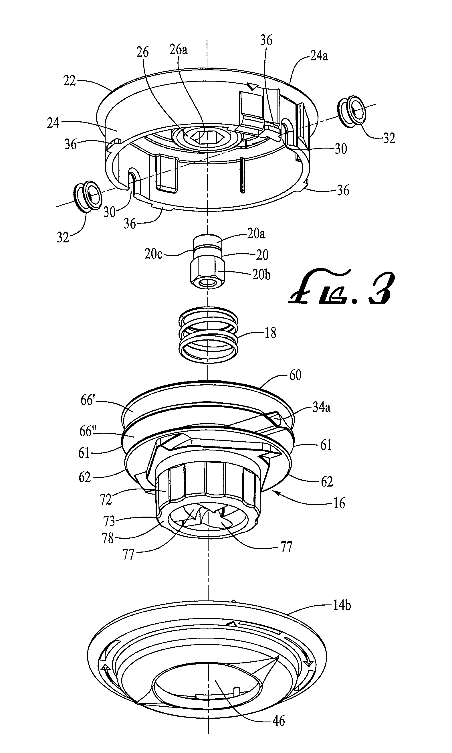
[0044]Referring now in detail to the drawings, a preferred embodiment of a bump-feed type trimmer head 10 of the type employing the spool of the present invention is shown in FIGS. 1-15. The trimmer head 10 of the present invention shown therein is designed to be mounted on the extended end of a rotatable drive shaft 12 on a gasoline or electric powered rotary trimmer (not shown). The trimmer head 10 shown therein is a bump-feed type head having the drive and line feeding mechanism disclosed in U.S. Pat. No. 4,959,904 and the rapid line loading and replacement feature disclosed in U.S. Pat. No. 7,797,839.

[0045]Trimmer head 10 comprises a housing 14, spool 16, coil spring 18 and drive bolt 20. The housing comprises an upper portion 14a and a lower portion 14b that are releasably secured together about the spool. The trimmer head housing and spool are preferably formed by injection molding a nylon 6 copolymer. The upper housing 14a defines an upper circular wall 22, a cylindrical hous...


PUM


Abstract

An improved spool construction for carrying a length of cutting line in a trimmer head housing on a flexible line rotary trimmer wherein the spool comprises separately molded upper and lower sections of single piece construction that are pressed together in a snap fitment to define a cylindrical body portion, at least one flange projecting radially therefrom and a line receptor channel having a smooth interior surface that traverses the spool and communicates opposed open outer channel ends in the flange that are radially alignable with opposed line openings in a housing skirt, with an open channel portion in a lower spool surface to provide access to the channel intermediary of the open channel ends with the spool operatively connected to the housing for line loading and replacement without having to interrupt the operative connection between the spool and the housing.

Description

CROSS-REFERENCE TO RELATED APPLICATIONS[0001]This application is a continuation-in-part of application Ser. No. 11 / 833,085, filed on Aug. 2, 2007 entitled “Trimmer Head for Use In Flexible Line Rotary Trimmers Having Improved Line Loading Mechanism” which claims priority from Provisional Application No. 60 / 824,404, filed on Sep. 1, 2006.BACKGROUND OF THE INVENTION[0002]The present invention relates to an improved spool construction for a trimmer head used in flexible line rotary trimming devices used to trim grass, weeds and other vegetation. More particularly, the invention is directed to an improvement in the construction of trimmer head spools of the type disclosed in U.S. Pat. No. 7,797,839 that allow new cutting line to be wound thereon and worn or broken line to be removed and replaced without having to separate the spool from the trimmer head housing.[0003]Trimmer heads used in flexible line rotary trimmers generally carry one or two lengths of flexible nylon cutting line wra...

Claims


Application Information

Patent Timeline
Patent Type & Authority Patents(United States)
IPC IPC(8): A01G3/06A01D34/416
CPCA01D34/4165A01D34/4166
Inventor PFALTZGRAFF, JAMES R.PROULX, RICHARD A.
Owner PROULX MFG
Why Eureka
Try Eureka