Safety barrier for multi-storey buildings

a safety barrier and multi-storey technology, applied in the field of buildings safety barrier systems, can solve the problems of high death rate of workers, and inability to meet the needs of construction, and achieve the effect of effectiv

Active Publication Date: 2013-08-20
DOUGALL CAMERON BRUCE +1
View PDF8 Cites 12 Cited by
  • Summary
  • Abstract
  • Description
  • Claims
  • Application Information

AI Technical Summary

Benefits of technology

[0005]The present invention provides a safety module having an elongated safety panel that can extend from one floor of a building structure and project upwardly above a superposed higher floor (working level) of the structure by an extent sufficient to constitute an effective safety barrier for that working level. The safety barrier panel is slidably mounted between a pair of side rails, enabling the safety barrier panel to be relocated upwardly, as a building progresses, floor by floor, with the safety bather panel also serving as a guide for the side rails, such that the safety barrier can be “walked” piecemeal up the side of a building, as the building progresses.
[0008]The subject system further includes toe boards of restricted depth, laterally coextensive with the safety barrier panel, and bridging a gap between the face of the safety barrier panel and the adjacent edge of the building floor, to contain articles from entering the gap. The subject system may further include safety barriers attachable to a floor inboard of the safety barrier panel system, to prevent unintended movement by an individual towards the subject safety barrier system. The safety barriers may be covered with a mesh to prevent material from falling from the enveloped floor.
[0010]The relative sliding relationship between the safety barrier panel and its side rails enables the safety barrier panel, when anchored to the structure, to serve as a slide guide for its respective side rails, enabling the side rails to be individually moved upwardly, by hand or by mechanical means to a higher floor and re-anchored. Correspondingly, the anchored and braced side rails serve as cantilevered guides for the respective safety barrier panel / panels.
[0012]Further characteristics of the present invention include duplexed side rails, wherein one of the side rails for one module is adjoined with the side rail of an adjacent module, into a unitary structure, thus facilitating coordinated relocation on a building. Also, an anchor bracket is provided for attachment to a selected building floor, the bracket being attachable by bolting or pinning to the duplexed side rails, and to each of the two associated safety barrier panels, independently of the side rails.
[0013]The subject anchor bracket is open-faced, enabling the independent vertical relocation of each safety barrier panel and the duplexed side rail track. The safety barrier panels and side rails can be pinned to the anchor brackets at intermediate locations along their lengths. This facilitates securing side rails in upwardly cantilevered relation, projecting up from anchor brackets on two floor levels.

Problems solved by technology

2. The history of constructing tall buildings is notoriously replete with the associated deaths of workers who fall from such structures.
Present day loss of lives, while not as scandalously high, is nevertheless too great.
The installation of such formwork and reinforcement necessitates working at a highly exposed, poorly protected working level.
Being mounted upon vertical tracks, the nets can be raised, floor by succeeding floor, as the building progresses upwardly, However, while the net may save a life, the support structure for the net itself constitutes a hazard for anyone falling onto it.
This latter system leaves open a dangerous accident ‘window’, until the succeeding floor has been poured, and the poles can be installed, which ‘windows’ constitute the most dangerous times of the building process, when workers are installing formwork and reinforcement while being totally unprotected against falling off the structure.

Method used


Image

  • Safety barrier for multi-storey buildings
  • Safety barrier for multi-storey buildings
  • Safety barrier for multi-storey buildings

Examples


Embodiment Construction

. OF THE INVENTION

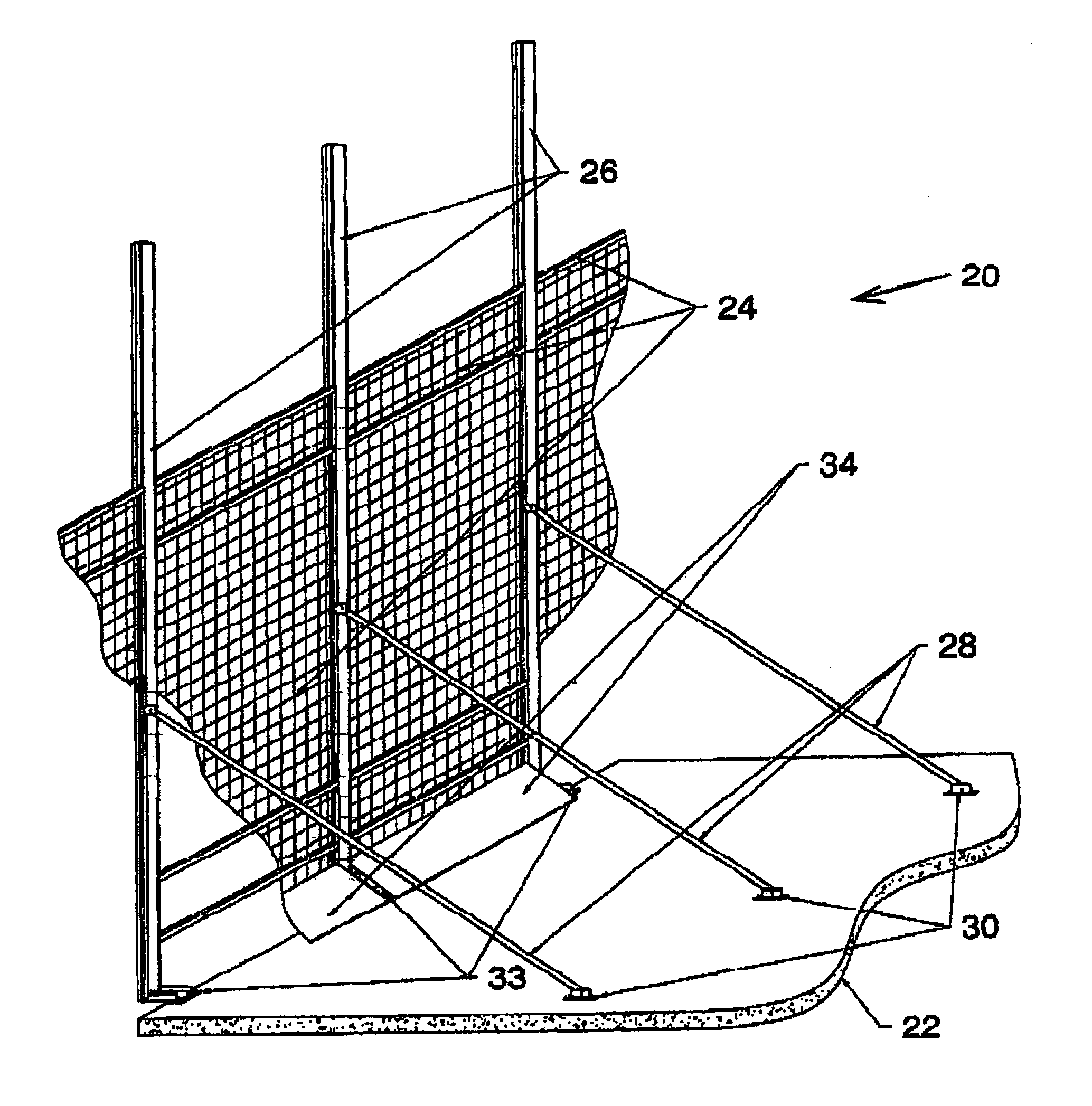
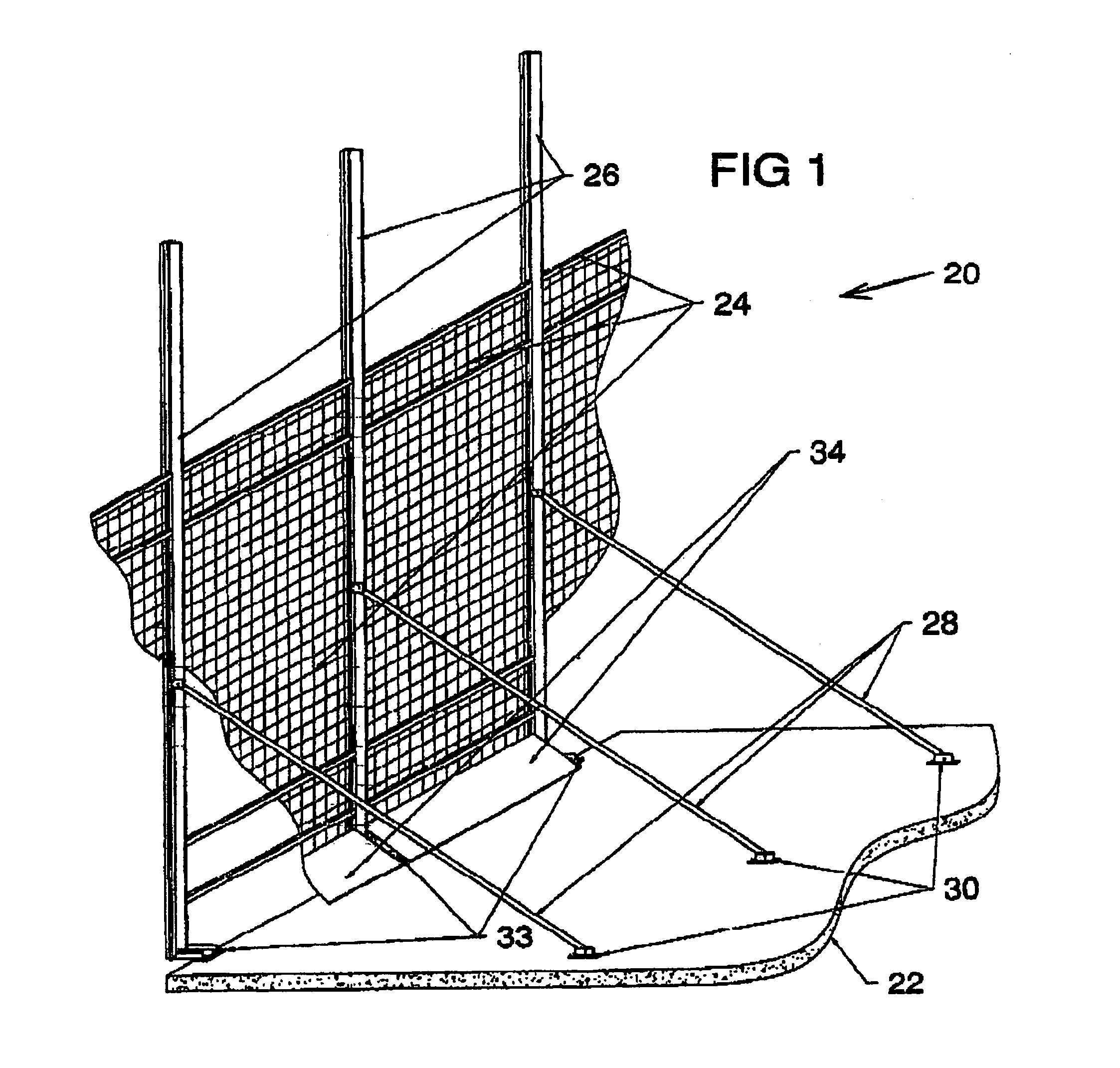
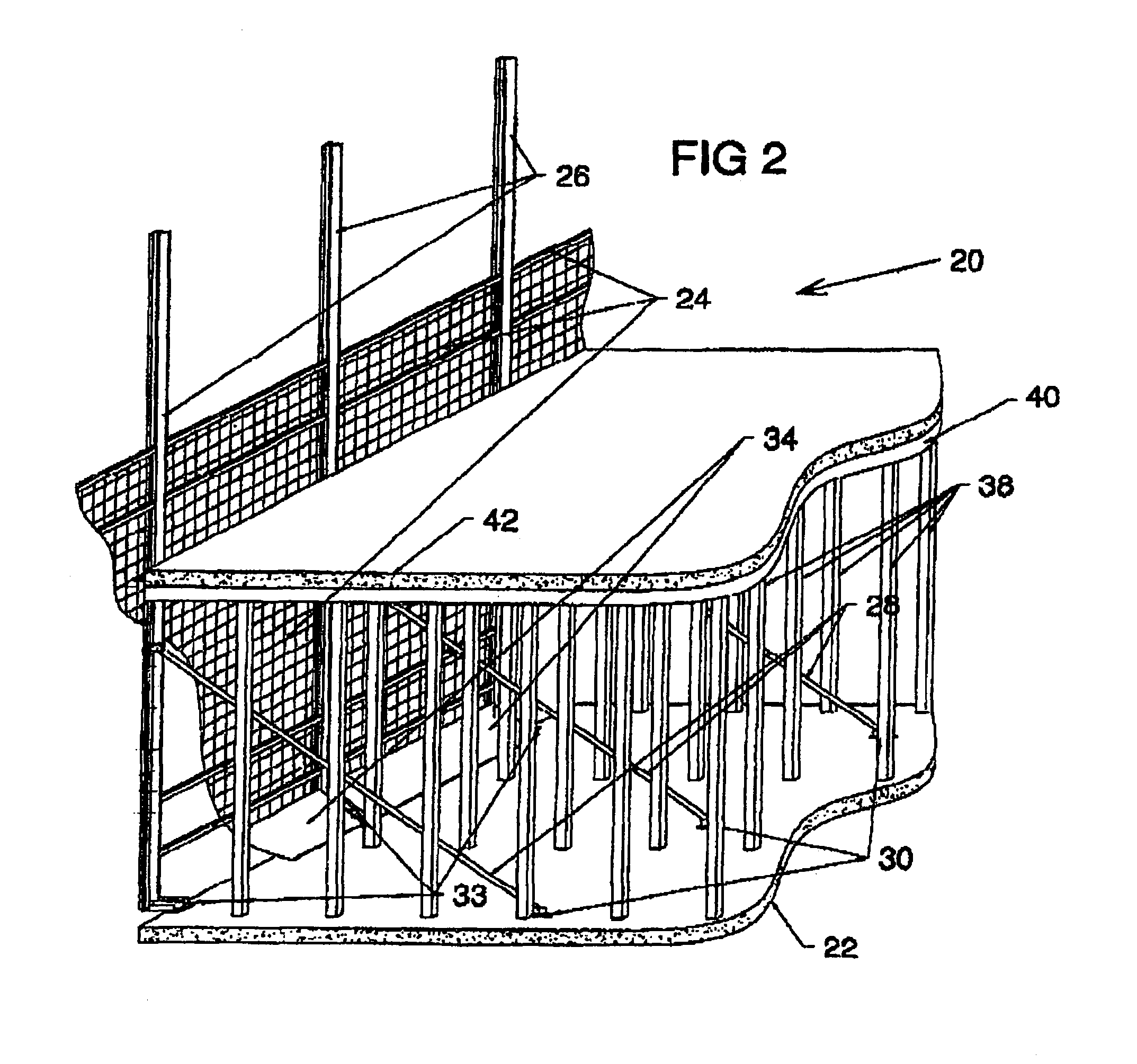
[0029]Referring to FIG. 1, this shows a side top perspective of the elements of an embodiment of the subject safety barrier system 20, wherein a safety barrier system 20 is shown mounted on a cast concrete floor 22 of a building under construction.

[0030]Safety bather panels 24 are slidably supported by side rails 26, of which the proximal side rails 26 are shown. Inclined braces 28 secure the assembly 20 in upstanding cantilevered relation from the poured concrete floor 22, the braces 28 being pinned to the safety barrier panels 24 and to brackets 30 that are screwed to the floor 22.

[0031]The lower ends of the side rails 26 are supported by being pinned to multi-bracket 33 at floor 22. The lower ends of the safety bather panels 24 are supported by being pinned to multi-bracket 33, which are bolted to the floor 22. A toe-board 34 which extends laterally coextensive with each safety barrier panel 24, and is attached thereto, serves to bridge the gap between each safe...


PUM


Abstract

A safety barrier system for use in constructing multi-storey buildings has elongated safety barrier panels extending upwards from a first floor level a sufficient height to serve as effective safety barriers during the work for the subsequent floor. The panels are supported at their side edges in rails along which the safety barrier panels can slide. The rails are duplexed (siamesed) so as to link the respective safety barrier panels into a continuous peripheral barrier. The respective panels and rails are braced and independently supported, permitting the system elements to be ‘walked’ piecemeal up the face of a structure as required during its erection. Auxiliary barriers supplement the displaced panels, on lower levels, while toe-boards protect the floor-to-panel gap.

Description

BACKGROUND OF THE INVENTION[0001]1. The present invention is directed to a safety barrier system for buildings, and in particular to a vertically extensible safety barrier for use in the construction of multi-storey buildings.[0002]2. The history of constructing tall buildings is notoriously replete with the associated deaths of workers who fall from such structures. In the case of the Empire State Building in New York City tradition has it that each floor of elevation accounted for the loss of a worker's life.[0003]Present day loss of lives, while not as scandalously high, is nevertheless too great. A common technique for building a high rise building is to erect formwork at ceiling height above an existing floor, lay reinforcement, and then pour concrete into the formwork to form the next floor. The installation of such formwork and reinforcement necessitates working at a highly exposed, poorly protected working level. Protective methods and apparatus currently in use include: low...

Claims


Application Information

Patent Timeline
Patent Type & Authority Patents(United States)
IPC IPC(8): E04B1/00E04G21/00E04G23/00E04B1/24E04B1/35E04B5/40E04G3/30E04G5/14E04G7/28
CPCE04G21/3219E04G21/3223E04B5/40E04B1/24E04B1/35E04G3/30E04G5/14E04G7/28E04G21/3247
Inventor DOUGALL, CAMERON BRUCEHESS, MARLOUS JUAN
Owner DOUGALL CAMERON BRUCE
Why Eureka
Try Eureka