Water vending apparatus

a water vending and water technology, applied in the field of purified water vending, can solve the problems of large volume, limited ability to serve this global need, and less affluent consumers are not well served by branded water, and achieve the effects of less production rate, less sedimentary buildup, and greater pump head pressur

Active Publication Date: 2013-08-20
DEKA PROD LLP
View PDF568 Cites 35 Cited by
  • Summary
  • Abstract
  • Description
  • Claims
  • Application Information

AI Technical Summary

Benefits of technology

[0028]Some embodiments of this aspect of the present invention may include one or more of the following. The water vending may be scalable. In differing markets, demand for a water vending apparatus may vary, giving rise to a larger or smaller apparatus performing essentially the same functions. A scaled down water vending apparatus may include scaled down dispensing and purification system components to accommodate a lesser production rate, for example. A scaled up water vending apparatus may include scaled up dispensing and purification components, or utilization of more than one purification system. The water vending apparatus may be divided into separate portions such that one or more portions may be operated remotely with respect to one or more other portions. Remote operation may necessitate extended conduits and control leads, greater pump head pressure, and / or integration of wireless communication components and protocols. The water vending apparatus may include a scale indicator to aid in preventing sedimentary buildup on surfaces exposed to hard water. The water vending apparatus may incorporate an extension hose and corresponding fill control apparatus. A filling hose may be beneficial in extending operable filling radius and general filling capability.

Problems solved by technology

There is a large, poorly satisfied global need for readily available, adequate tasting, safe, affordable and convenient drinking water.
The ability to serve this global need is limited by many factors, one being the economics of the centralized bottling model.
Traditionally, less affluent consumers are not well served by branded water as price increases with respect to water quality and trustworthiness.
Distributed purification alternatives, such as chemical treatment and carbon filtration, have limited impact on water safety and have significant limitations for consumers, retailers, bottlers, and brand owners.
Water kiosks, i.e., locations, providing containers of water which are typically filled at an off-site location and transported to the kiosk, are prevalent in cities with poor municipal water supplies, and are an inefficient and expensive solution to providing safe drinking water to the masses.
Environmentally, transport of kiosk-related water jugs increases pollution and traffic congestion.
Additionally, the volume of water capable of being stored at a kiosk in jug-form is finite.

Method used


Image

  • Water vending apparatus
  • Water vending apparatus
  • Water vending apparatus

Examples


Embodiment Construction

[0264]Definitions. As used in this description and the accompanying claims, the following terms shall have the meanings indicated, unless the context otherwise requires.

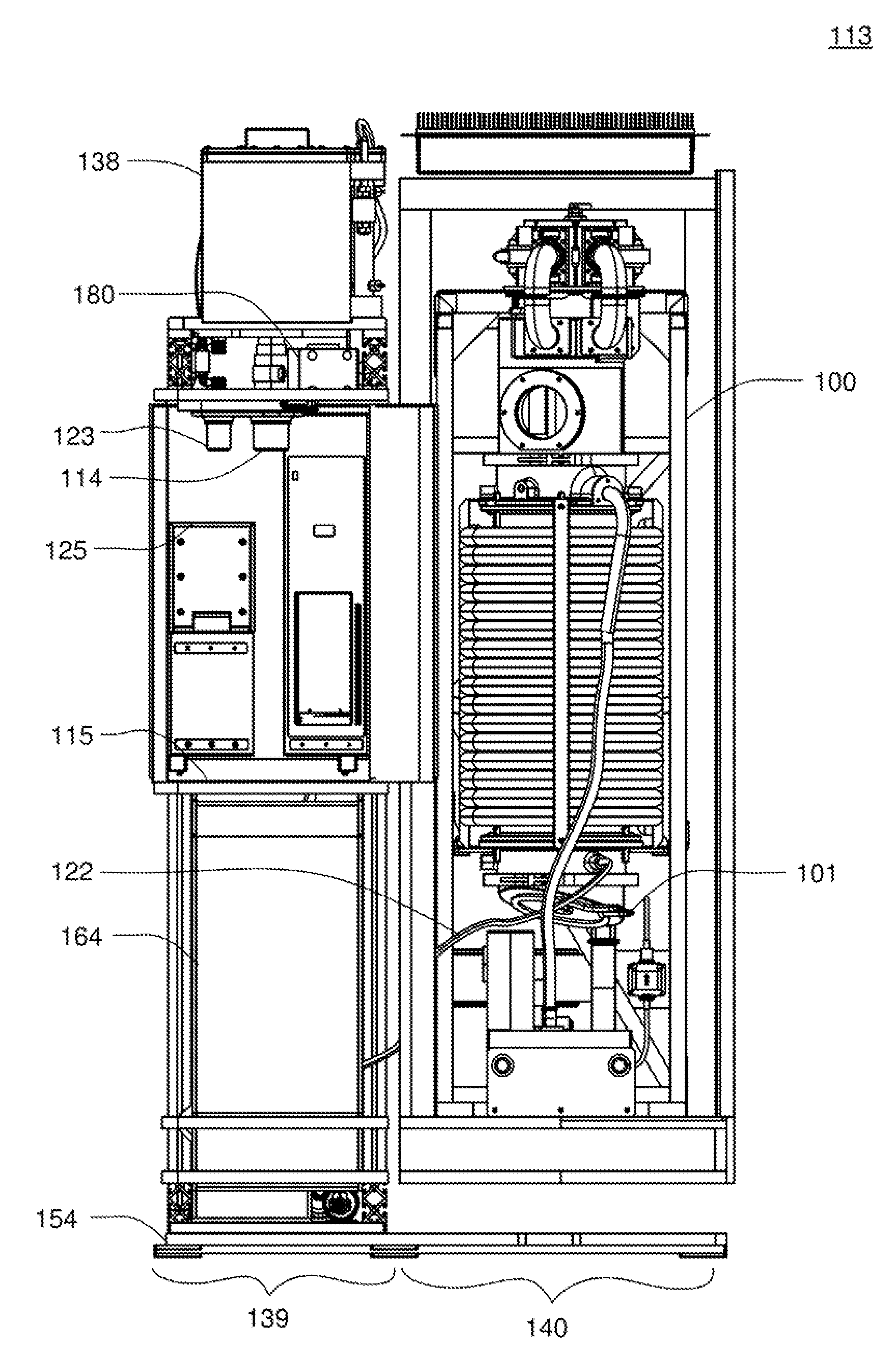
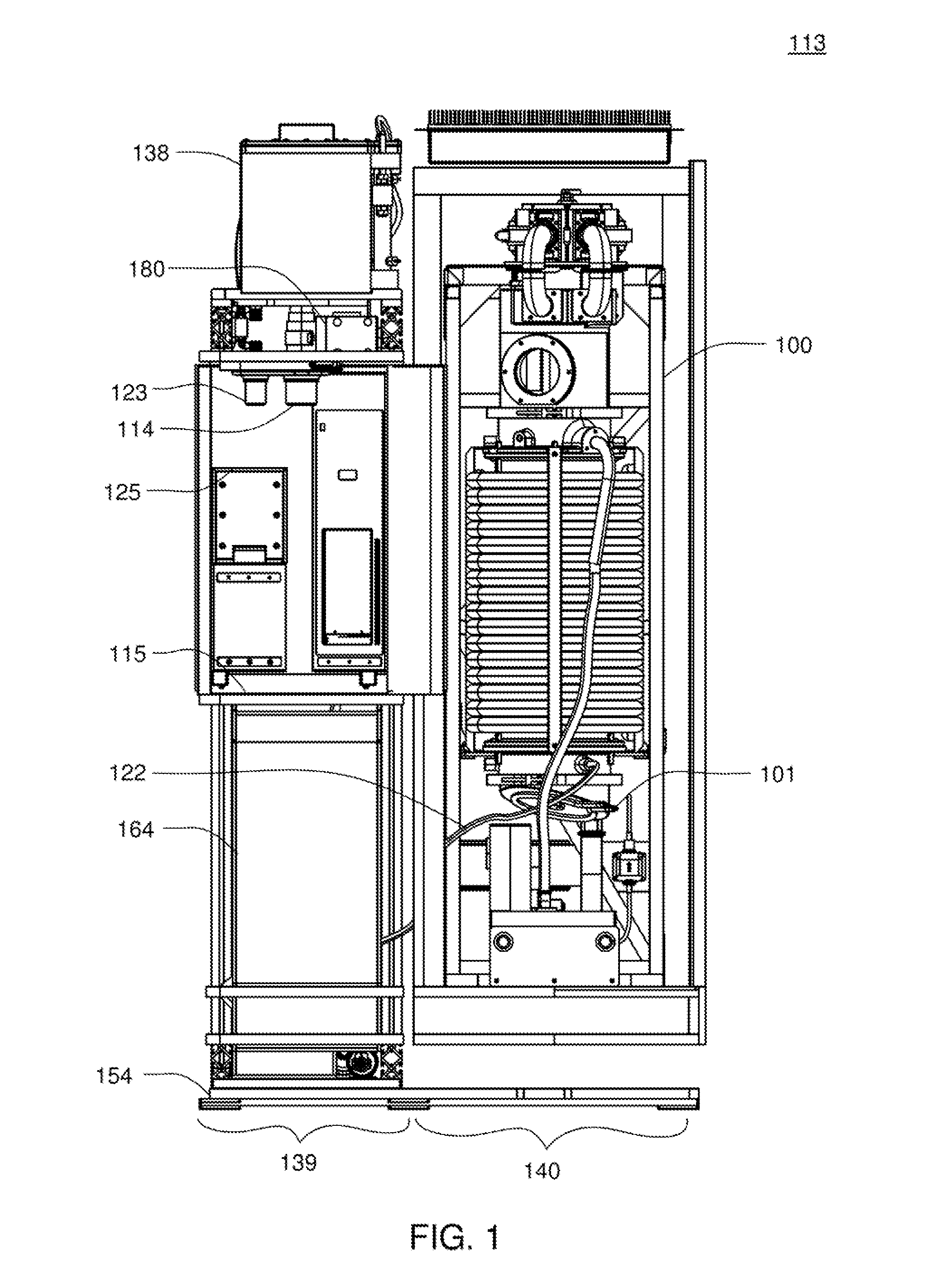
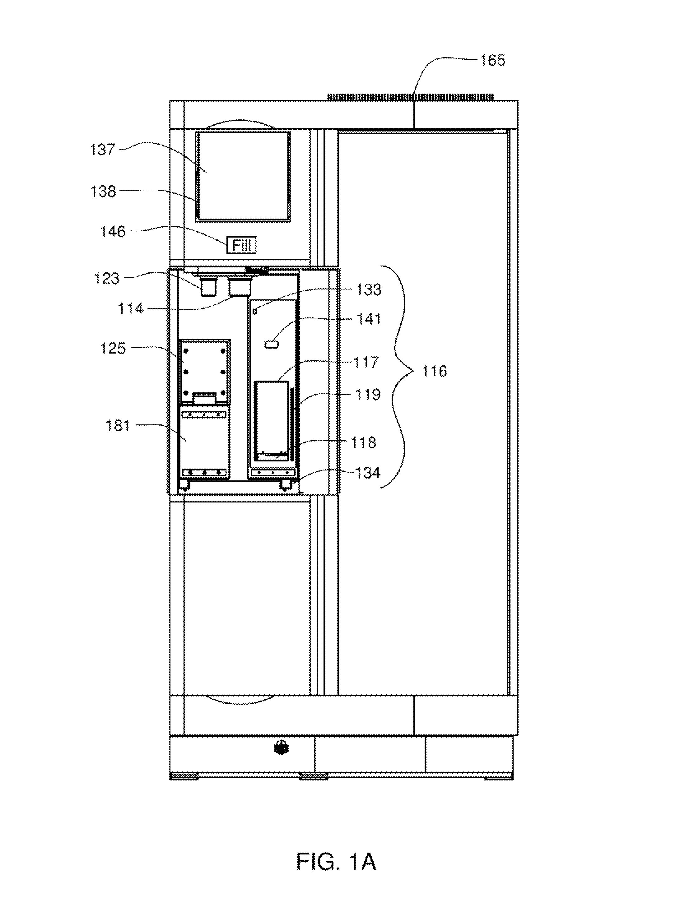
[0265]The term “evaporator condenser” is used herein to refer to an apparatus that is a combination evaporator and condenser. Thus, a structure is referred to as an evaporator condenser where the structure itself serves as both. The evaporator condenser structure is referred to herein as an evaporator / condenser, evaporator condenser or evaporator and condenser. Further, in some instances, where either the evaporator or the condenser is being referred to individually, it should be understood that the term is not limiting and refers to the evaporator condenser structure.

[0266]The term “fluid” is used herein to include any type of fluid including water. Thus, although the exemplary embodiment and various other embodiments are described herein with reference to water, the scope of the apparatus, system and methods includ...


PUM


Abstract

A water vending apparatus is disclosed. The water vending system includes a water vapor distillation apparatus and a dispensing device. The dispensing device is in fluid communication with the fluid vapor distillation apparatus and the product water from the fluid vapor distillation apparatus is dispensed by the dispensing device.

Description

CROSS REFERENCE TO RELATED APPLICATIONS[0001]The present application is a Non-Provisional Application which claims priority from U.S. Provisional Patent Application Ser. No. 61 / 089,295, filed Aug. 15, 2008 and entitled Water Vending Apparatus Having Water Vapor Distillation Purification System, which is hereby incorporated herein by reference in its entirety.[0002]The present application is also a Continuation In Part Application of U.S. patent application Ser. No. 12 / 135,035, filed Jun. 6, 2008 and entitled Water Vapor Distillation Apparatus, Method and System, which claims priority from U.S. Provisional Patent Application 60 / 933,525, filed Jun. 7, 2007 and entitled Water Vapor Distillation Apparatus, Method and System, and is also a Continuation-In-Part of patent application Ser. No. 11 / 480,294 filed Jun. 30, 2006 and entitled Pressurized Vapor Cycle Liquid Distillation which is a Continuation-In-Part of patent application Ser. No. 10 / 713,617 filed Nov. 13, 2003 and entitled Press...

Claims


Application Information

Patent Timeline
Patent Type & Authority Patents(United States)
IPC IPC(8): F25D21/14
CPCB01D1/28B01D5/006B67D1/0862C02F1/16B67D1/0014C02F1/048Y02W10/37B01D1/2887C02F1/041C02F1/325C02F2303/04C02F2303/10
Inventor KAMEN, DEANLANGENFELD, CHRISTOPHER C.LAROCQUE, RYAN K.SCHNELLINGER, ANDREW A.BHAT, PRASHANTSMITH, III, STANLEY B.CLAPP, OTIS L.SWERDLOW, JEREMY M.
Owner DEKA PROD LLP
Why Eureka
Try Eureka