Wedge driven pipe bending machine

a bending machine and bending pipe technology, applied in the field of pipe bending equipment, can solve the problems of plastic deformation of the pipe, impose serious limitations on the capabilities of the machine, and increase the likelihood of leakage and other defects in the operation of the cylinder, so as to reduce the required hydraulic force

Inactive Publication Date: 2013-08-20
CRC EVANS PIPELINE INT INC
View PDF9 Cites 1 Cited by
  • Summary
  • Abstract
  • Description
  • Claims
  • Application Information

AI Technical Summary

Benefits of technology

[0008]Preferably, the pipe bending face is on a downstream portion of the die as the pipe is longitudinally transferred through the machine. The first fulcrum is downstream of the upstream portion of the pipe bending face and facilitates rotation about the first axis and perpendicular to the longitudinal axis of the pipe. The second fulcrum is downstream of the first fulcrum and facilitates rotation about a second axis parallel to said first axis.
[0014]A pipe bender in accordance with this invention reduces the required hydraulic force by a factor in a range of 4:1 in comparison to known pipe bending machines. It reduces the forces exerted by the cylinder and the opportunity for leaks and defects. It puts the cylinders in a linear non-competing, non-binding configuration.

Problems solved by technology

Each pull results in a plastic deformation of the pipe.
Such a requirement imposes serious limitations on capabilities of the machine.
First, the larger the diameter of the cylinder, the greater will be the likelihood of leakage and other defects in cylinder operation.
Third, even though the custom cylinders are very large, known machines still require the use of tandem cylinders tied together.
This results in the cylinders competing with each other, reducing the net bending force available.
In the worst such cases, the counteracting cylinders may bind.
Fourth, the resulting reduced cylinder diameter to stroke ratio can cause the stiff-back to overshoot the intended bending angle of the pipe due to reduced controllability.

Method used


Image

  • Wedge driven pipe bending machine
  • Wedge driven pipe bending machine
  • Wedge driven pipe bending machine

Examples


Embodiment Construction

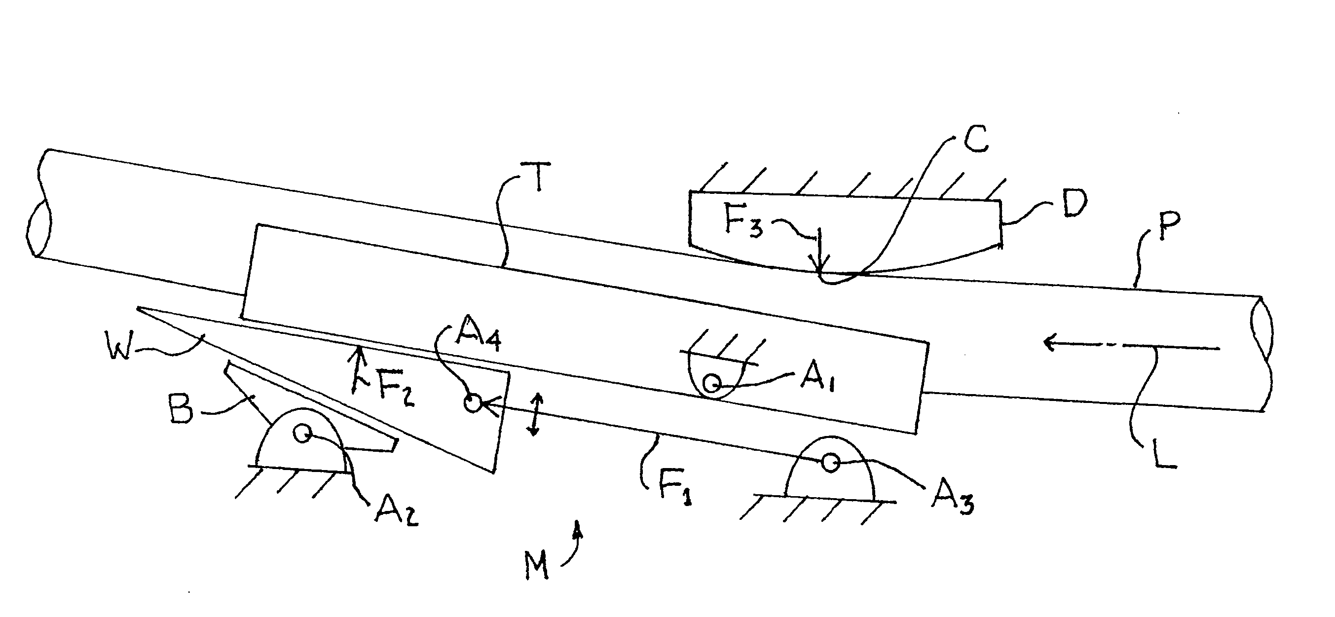
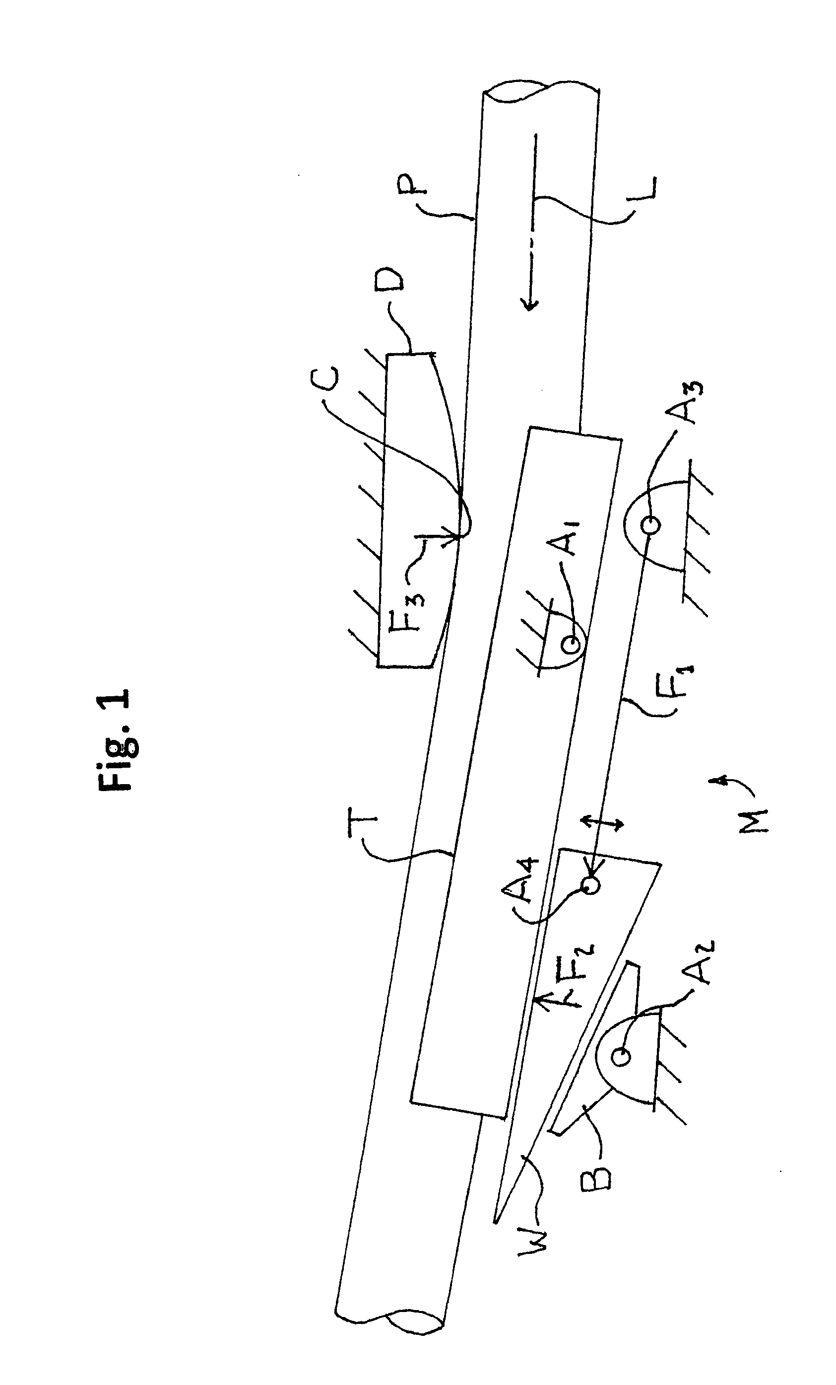
[0032]Turning first to FIG. 1, the pipe P is to be bent against a die D. The pipe P will be advanced along its longitudinal axis L in a downstream direction in incremental steps past the die D. “Downstream direction” is relative and describes the movement of the pipe P in relation to the machine M. In practice, the machine M moves upstream in relation to the pipe P which is stationary. The pipe P is initially advanced to a position at which it can be rested in a trough T, commonly referred to as a stiff-back, which extends longitudinally downstream of the die D. The trough T is pivoted on a first axis A1, as shown on the upstream portion of the trough T below the die D but downstream of the anticipated contact point C of the pipe P with the die D. The downstream end of the trough T is supported by a wedge W which is supported by and reciprocally slides on a bed B which is pivoted on a second axis A2. When the pipe P is in the initial position, a wedge driving force F1 which is direc...


PUM

PropertyMeasurementUnit
forceaaaaaaaaaa
plastic deformationaaaaaaaaaa
diameteraaaaaaaaaa

Abstract

A pipe bending machine has a stiff-back which is driven by a pivoting wedge. A linkage applies force from the actuator to the wedge in a direction parallel to a longitudinal axis of the stiff-back. The stiff-back pivots on a first fulcrum and the wedge slides on a bed which pivots on a second fulcrum. The actuator drives the wedge between the stiff-back and the bed to rotate the stiff-back at the first fulcrum and bend the pipe seated in the stiff-back against the pipe bending face of a die. The conversion of the longitudinal force applied to the wedge into a transverse force applied to the stiff-back provides a significant mechanical advantage which varies directionally as the stiff-back rotates about its fulcrum to maintain a constant force on the stiff-back.

Description

BACKGROUND OF THE INVENTION[0001]This invention relates generally to pipe bending equipment and more particularly concerns machines used to bend steel pipe.[0002]Known pipe bending machines level a pipe against a die with a pin-up located on one side of the die and apply force to the pipe on the other side of the die with a stiff-back, typically powered by hydraulic cylinders, to bend the pipe against the die. The maximum bend typically totals 15-16° and the total is achieved by sequential pulls. In each pull, the pipe is bent approximately ½°. Each pull results in a plastic deformation of the pipe. The cylinders of known machines apply the force directly to the stiff-back. Therefore, known machines generally require large diameter cylinders capable of generating forces in a range of 750,000 pounds. Typically, the cylinders required are in the range of 9-14″ in diameter. Such a requirement imposes serious limitations on capabilities of the machine.[0003]First, the larger the diamete...

Claims


Application Information

Patent Timeline
Patent Type & Authority Patents(United States)
IPC IPC(8): B21D7/10
CPCB21D7/022B21D7/00B21D7/0225B21D7/06
Inventor SCOVILLE, JEFFREY C.GWARTNEY, TIMOTHY R.SEARS, STEPHEN
Owner CRC EVANS PIPELINE INT INC
Why Eureka
Try Eureka