RFID integrated circuit to strap mounting system

a technology of integrated circuits and mounting systems, which is applied in the direction of semiconductor devices, semiconductor/solid-state device details, instruments, etc., can solve the problems of inability to apply consistent and inability to achieve uniform force during the attachment process. achieve the effect of similar performance characteristics

Active Publication Date: 2013-08-20
IMPINJ
View PDF6 Cites 18 Cited by
  • Summary
  • Abstract
  • Description
  • Claims
  • Application Information

AI Technical Summary

Benefits of technology

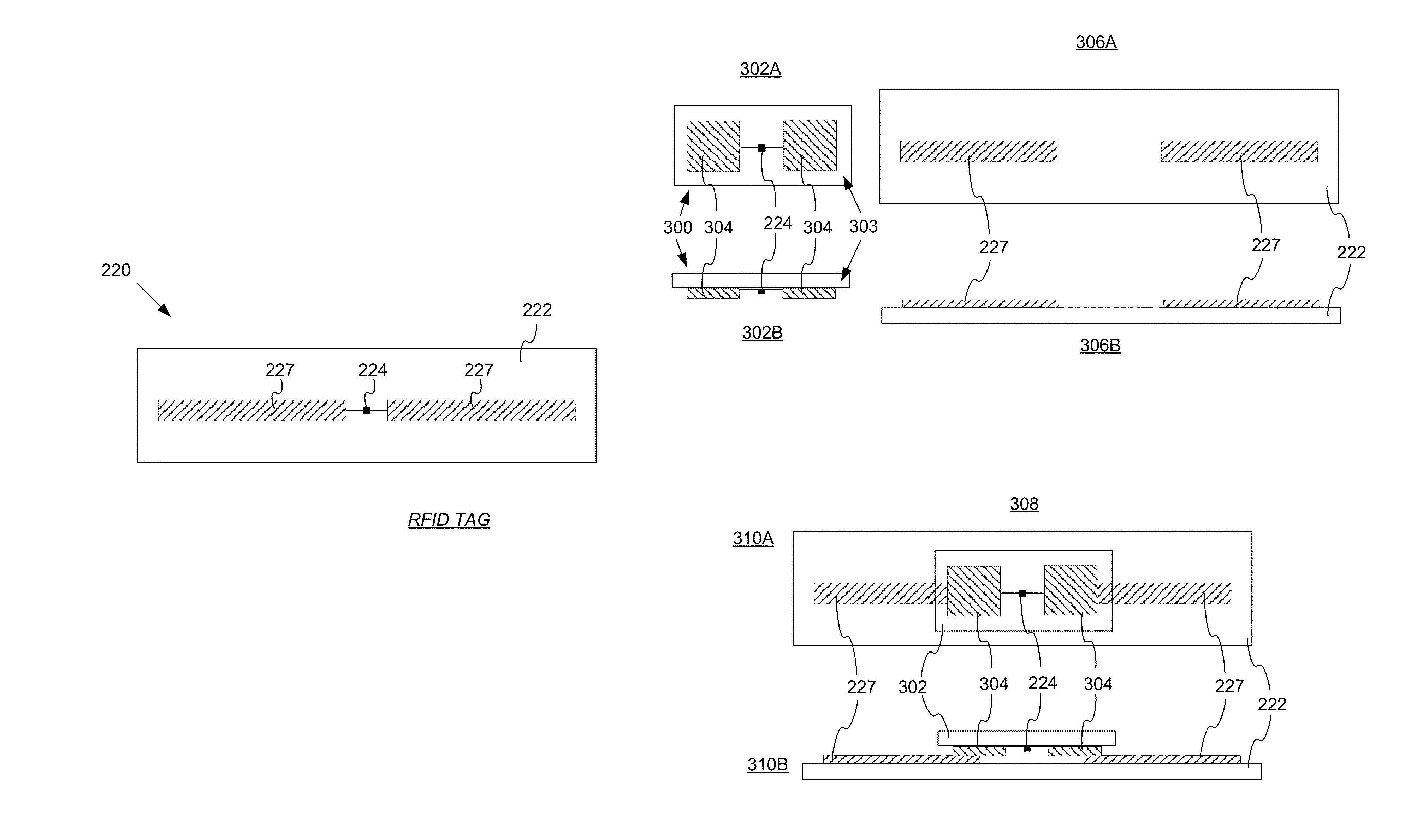
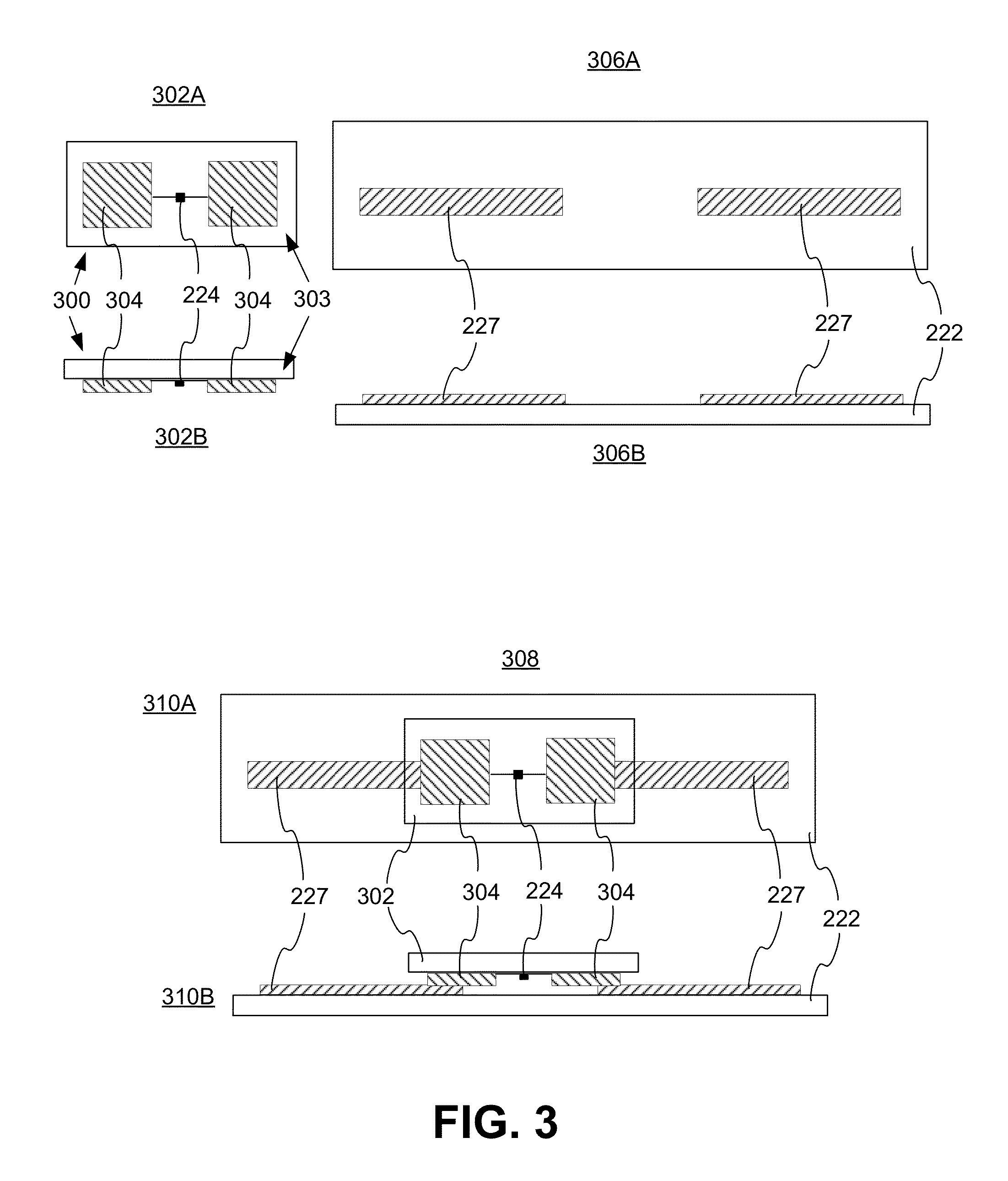
[0011]Embodiments are directed to RFID tags and methods of manufacturing RFID tags employing a stabilization layer for consistent and predictable mounting distance between an RFID IC and its antenna layer or a strap. A nonconductive, organic stabilization layer with a predefined thickness is formed over the RFID IC. Openings are formed in the stabilization layer for antenna connections. According to some embodiments, bumps may be formed on the RFID IC over the antenna connections such that the bumps establish electrical connection between the RFID circuits and the antenna layer or strap contacts when an inlay including the antenna layer or a strap with strap contacts is pressed against the RFID IC. The stabilization layer ensures consistent mounting distance between the antenna layer / strap contacts and the RFID circuits resulting in consistent and predictable distributed capacitance between the two, thereby producing tags with substantially similar performance characteristics.

Problems solved by technology

In some instances the machines may not apply consistent force during the attachment process.
The mounting capacitance affects the performance of the RFID tag.
Tags with different mounting capacitance have undesired performance variations in RFID applications.

Method used


Image

  • RFID integrated circuit to strap mounting system
  • RFID integrated circuit to strap mounting system
  • RFID integrated circuit to strap mounting system

Examples


Embodiment Construction

[0033]In the following detailed description, references are made to the accompanying drawings that form a part hereof, and in which are shown by way of illustration specific embodiments or examples. These embodiments or examples may be combined, other aspects may be utilized, and structural changes may be made without departing from the spirit or scope of the present disclosure. The following detailed description is therefore not to be taken in a limiting sense, and the scope of the present invention is defined by the appended claims and their equivalents.

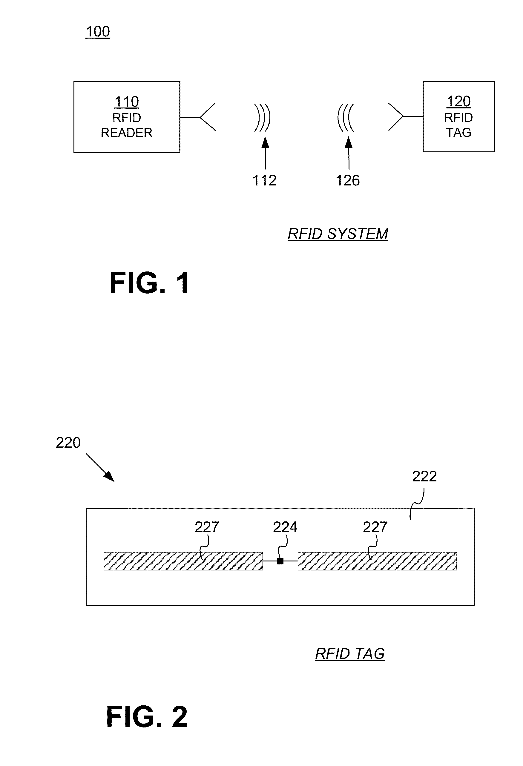
[0034]FIG. 1 is a diagram of components of a typical RFID system 100, incorporating embodiments. An RFID reader 110 transmits an interrogating Radio Frequency (RF) wave 112. RFID tag 120 in the vicinity of RFID reader 110 may sense interrogating RF wave 112 and generate wave 126 in response. RFID reader 110 senses and interprets wave 126.

[0035]Reader 110 and tag 120 exchange data via wave 112 and wave 126. In a session of such an e...


PUM


Abstract

A nonconductive, organic stabilization layer deposited on an RFID IC provides a consistent and predictable mounting distance between the RFID IC and its antenna layer or a strap, thereby ensuring a consistent and predictable mounting capacitance between circuits of the RFID IC and an antenna formed on the inlay or the strap. Openings in the stabilization layer enable electrical connection between the antenna pads of the RFID IC and the terminals of the inlay antenna or strap contacts through bumps formed on the antenna pads, through a conductive redistribution layer formed on the stabilization layer (when the inlay or strap is attached to the RFID IC by means of an anisotropic conductive layer), or through a capacitive connection to the inlay antenna or strap (when the inlay or strap is attached to the RFID IC by means of a nonconductive layer).

Description

CROSS REFERENCE TO RELATED APPLICATIONS[0001]This application is a continuation-in-part of U.S. patent application Ser. No. 12 / 938,092 filed on Nov. 2, 2010. The disclosures of the foregoing patent application are hereby incorporated by reference for all purposes.BACKGROUND[0002]Radio Frequency Identification (RFID) systems typically include RFID tags and RFID readers. RFID readers are also known as RFID reader / writers or RFID interrogators. RFID systems can be used in many ways for locating and identifying objects to which the tags are attached. RFID systems are particularly useful in product-related and service-related industries for tracking objects being processed, inventoried, or handled. In such cases, an RFID tag is usually attached to an individual item, or to its package.[0003]In principle, RFID techniques entail using an RFID reader to interrogate one or more RFID tags. The reader transmitting a Radio Frequency (RF) wave performs the interrogation. The RF wave is typically...

Claims


Application Information

Patent Timeline
Patent Type & Authority Patents(United States)
IPC IPC(8): H01L23/02
CPCG06K19/07752G06K19/07754G06K19/07786H01L2224/16227H01L2924/07811H01L2224/16225H01L2924/00H01L2924/00014H01L2224/0401
Inventor KOEPP, RONALD L.HEINRICH, HARLEY K.DIORIO, CHRISTOPHER J.
Owner IMPINJ
Why Eureka
Try Eureka