RFID reader having an array of antennas

a technology of antenna array and reader, applied in the direction of sensing record carriers, instruments, sensing electromagnetic radiation, etc., can solve the problems of unidentifiable samples, easy erasement or smudging of written notes on containers, and exacerbated problems

Active Publication Date: 2015-05-07
CRYOGATT SYST
View PDF2 Cites 13 Cited by
  • Summary
  • Abstract
  • Description
  • Claims
  • Application Information

AI Technical Summary

Problems solved by technology

However, these methods of identification have associated disadvantages; written notes on containers can easily be erased or smudged and labels containing handwritten notes and printed text or barcode information can fall off the disposable containers while they are stored inside the Dewar leading to unidentifiable samples.
These problems are exacerbated by the cold conditions in which biological samples must be kept.
Recording, monitoring and auditing of samples in cold storage takes a considerable amount of time and effort, even when samples are labelled using barcodes.
An additional and undesirable increase in the time taken to record or audit samples arises as a result of frost which forms on the surfaces of disposable containers and their labels when they are removed from liquid nitrogen into relatively warmer temperatures.

Method used


Image

  • RFID reader having an array of antennas
  • RFID reader having an array of antennas
  • RFID reader having an array of antennas

Examples


Embodiment Construction

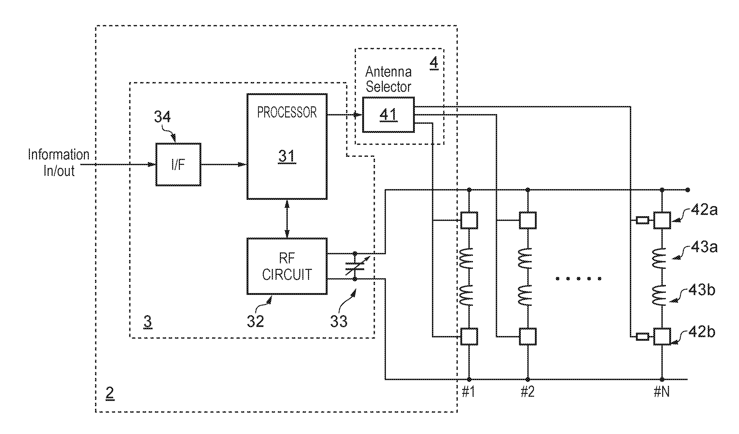
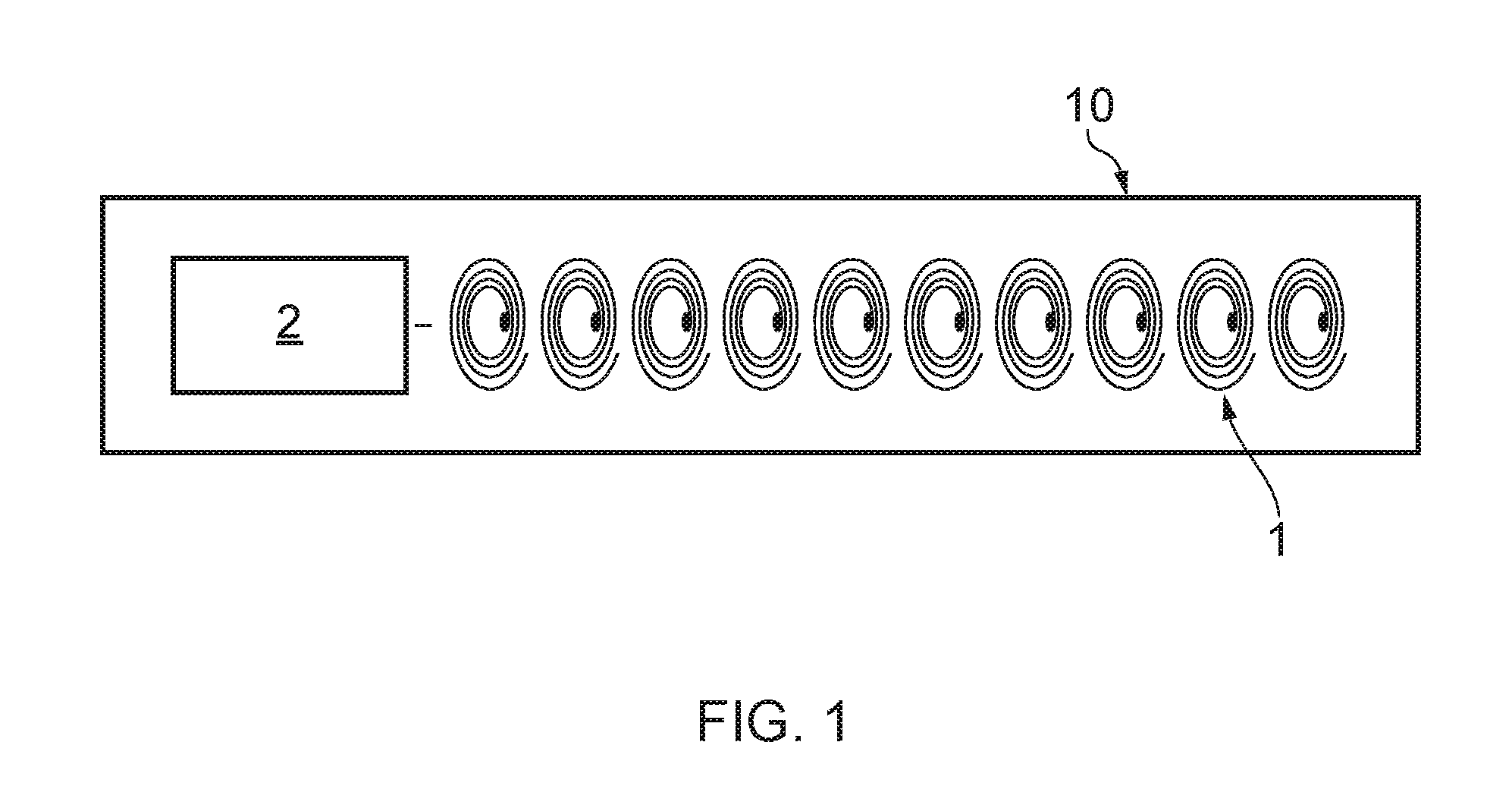
[0039]A first embodiment of an RFID reader, 10 according to the present invention is shown in FIG. 1. A strip (row) of 10 multilayer antennas 1 forms a 1×10 array. The multilayer antennas are connected to one another in parallel (see FIG. 3) so that each multilayer antenna is connected to an electronics unit 2 via at least one switch. The electronics unit controls the writing of information to and the reading of information from RFID tags.

[0040]Each antenna 1 is configured to interact on a one-to-one basis with an RFID tagged vial via inductive coupling. The RFID reader may be configured only to read each of a plurality of tagged vials or alternatively may be configured to both read and write to each of a plurality of tagged vials.

[0041]To read each of a plurality of vials placed in proximity to the RFID reader 10, an interrogation command signal is sent from the reader to the individual RFID tagged vial via its dedicated multilayer antenna.

[0042]In the case where the RFID reader ca...


PUM


Abstract

An RFID reader for tracking a plurality of RFID tags, the RFID reader comprising an array of multilayer antennas each multilayer antenna comprising a first coil and a second coil, the first coil being superimposed above the second coil; and an electronics unit configured to transmit a signal to and receive and process information from each multilayer antenna.

Description

TECHNICAL FIELD[0001]The present invention relates to a reader for RFID tracking, particularly RFID tracking of biological material stored in vials at low temperatures (e.g. temperatures of below −130° C.)BACKGROUND[0002]Biological samples may be preserved by cryogenic freezing. The biological samples are usually stored in disposable containers (disposables). The shape of the disposable container used depends on the type of sample. Examples of commonly used disposable containers include vials, straws and bags. The disposable container is stored at low temperatures in a Dewar flask, usually filled with liquid nitrogen at a temperature of −196° C.[0003]Stored biological samples can be identified by writing on the disposable containers themselves, or by labels stuck to the containers. These labels may be handwritten or printed and can include bar codes. However, these methods of identification have associated disadvantages; written notes on containers can easily be erased or smudged an...

Claims


Application Information

Patent Timeline
IPC IPC(8): G06K7/10
CPCG06K7/10336G06K7/10356
Inventor MORRIS, GEOFFREYDOUGLAS, JAMES
Owner CRYOGATT SYST
Why Eureka
Try Eureka