Structural mode shape alignment

a technology of structural mode and shape alignment, which is applied in the field of system and method for reducing noise within the cabin, can solve the problems of increasing the weight of the mobile platform, and its cost of manufacture, and achieve the effect of reducing noise in the cabin

Active Publication Date: 2013-08-20
FUJIFILM HEALTHCARE CORP +1
View PDF14 Cites 6 Cited by
  • Summary
  • Abstract
  • Description
  • Claims
  • Application Information

AI Technical Summary

Benefits of technology

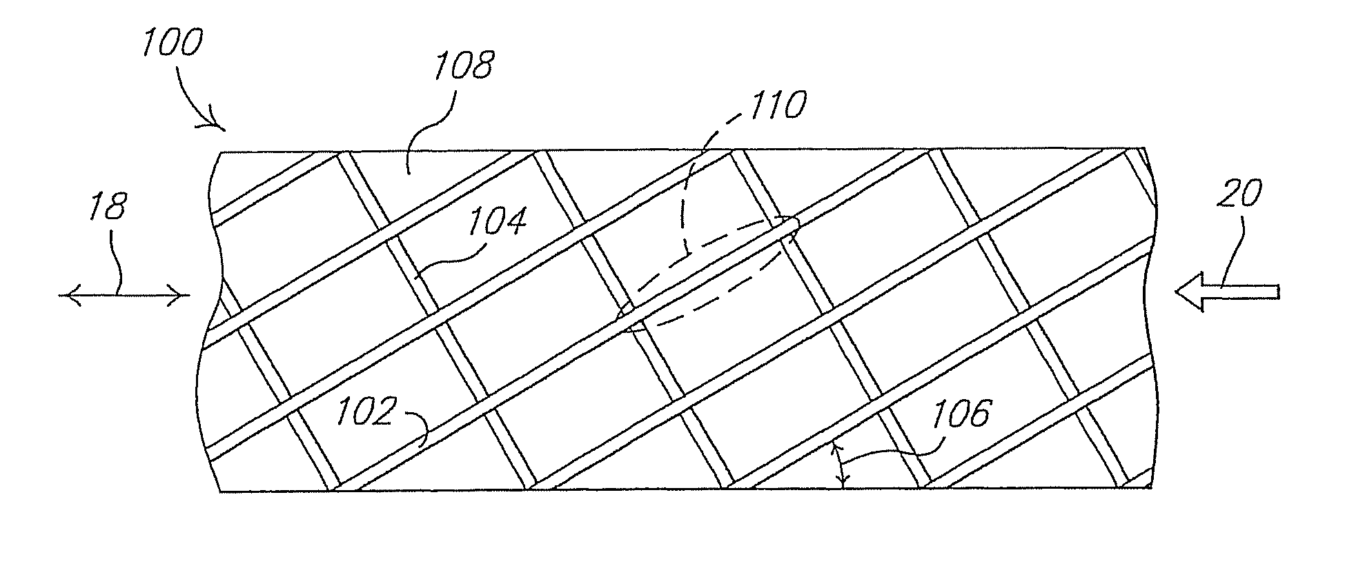
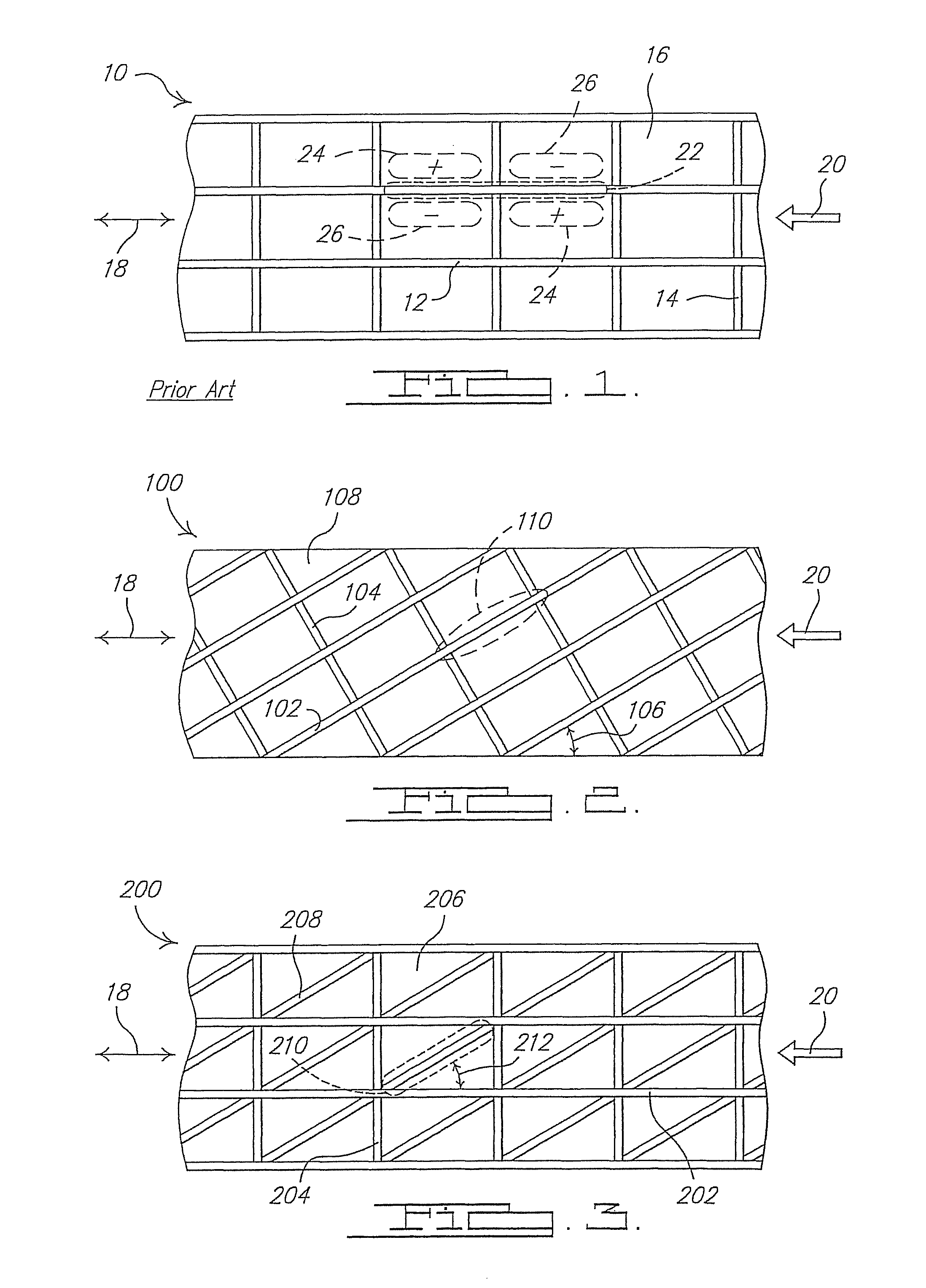
[0008]By orientating the stringers and frame members of the fuselage such that a fundamental skin panel vibration mode shape is produced that is non-parallel to the direction of the boundary layer flow, a reduction in noise within the cabin of the mobile platform, caused by the turbulent boundary layer flow, can be achieved.

Problems solved by technology

As will be appreciated, the adding of insulation increases the weight of the mobile platform, as well as its cost of manufacture.

Method used


Image

  • Structural mode shape alignment
  • Structural mode shape alignment
  • Structural mode shape alignment

Examples


Embodiment Construction

[0021]The following description of the preferred embodiment(s) is merely exemplary in nature and is in no way intended to limit the invention, its application, or uses.

[0022]Referring to FIG. 1, there is shown a prior art illustration of a representative portion of a fuselage 10 of a mobile platform, in this example a commercial jet aircraft, in accordance with a prior art construction of the fuselage. The fuselage 10 incorporates a plurality of stringers 12 and frame members 14 that support a skin panel 16. The stringers 12 are oriented generally parallel to a longitudinal axis 18 of the fuselage 10. It has been determined through testing and analysis that this arrangement of frames and stringers produces a fundamental panel vibration mode shape for the skin panel 16 that is aligned generally parallel to a major streamline of the direction of the turbulent boundary layer. This is indicated in simplified fashion by dashed line 22, and the major streamline of the turbulent boundary l...


PUM

PropertyMeasurementUnit
angleaaaaaaaaaa
angleaaaaaaaaaa
natural frequencyaaaaaaaaaa

Abstract

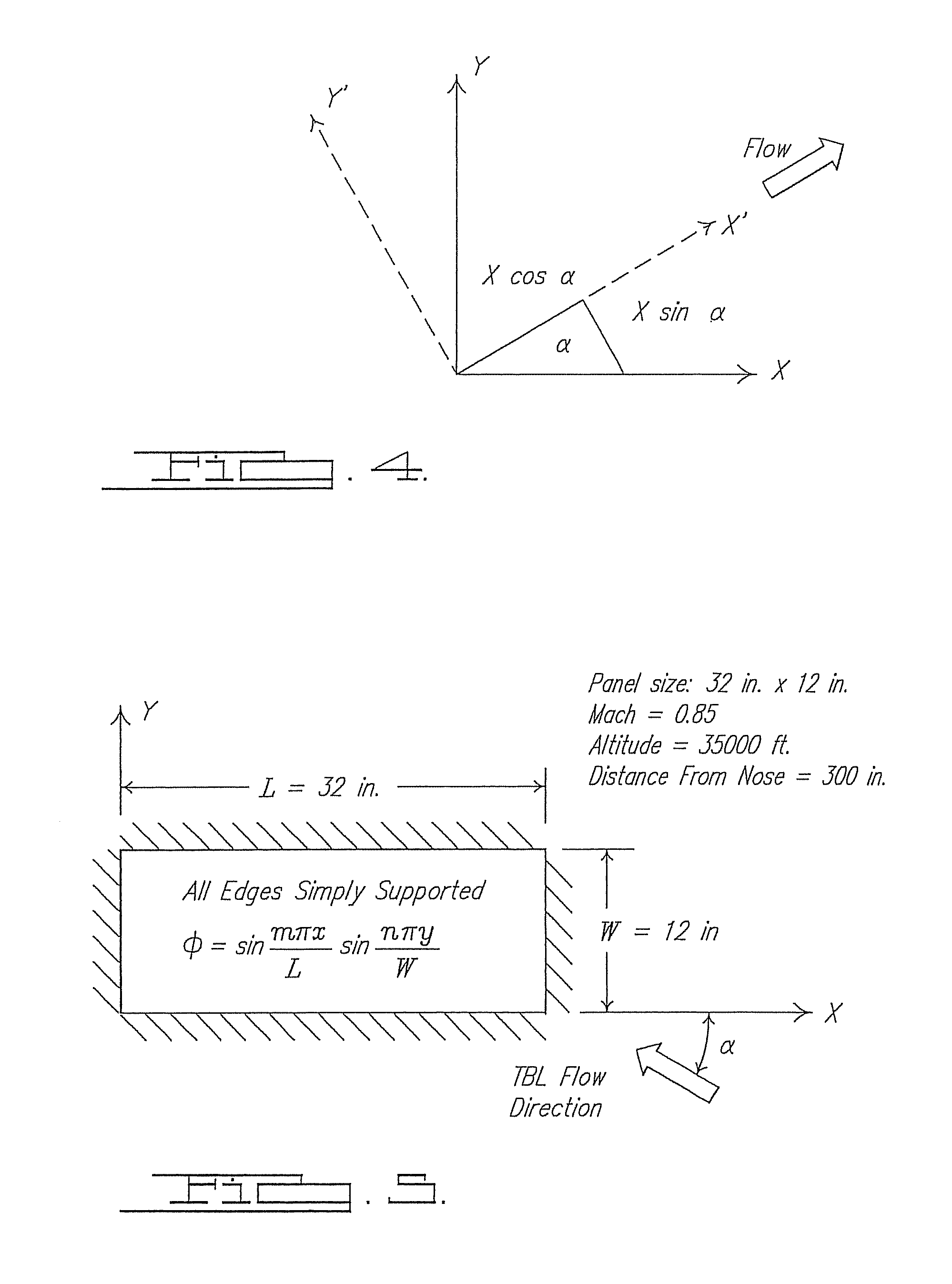
Apparatus and method for controlling the orientation of a fundamental panel vibration mode shape of a structure, such as a skin panel of a fuselage of an aircraft, relative to the direction of a turbulent boundary layer flow over the fuselage, and in a manner to achieve a level of noise reduction within the fuselage. The fuselage is constructed either through orientating stringers and / or frame members, or by using stiffening members placed diagonally between the stringers and frame members, in a manner that produces a fundamental panel vibration mode shape that extends at an angle of between about 30°-45° relative to the direction of the turbulent boundary layer flow over the fuselage. Aligning the fundamental panel vibration mode shape at an angle of between about 30°-45° relative to the direction of the turbulent boundary layer flow results in a reduction of the vibration response of the skin panel, and thus a reduction in the noise level within the fuselage.

Description

FIELD OF THE INVENTION[0001]The present invention relates to systems and methods for ameliorating noise, and more particularly, to a system and method for ameliorating noise within a high speed mobile platform, in which the noise is caused in large part by the turbulent boundary layer air flow over a skin panel structure of the mobile platform.BACKGROUND OF THE INVENTION[0002]With various forms of commercial platforms in which passengers are transported, minimizing noise inside a cabin of the mobile platform is an important consideration. In applications involving commercial passenger aircraft, this is an especially important consideration. The cabin noise within a commercial aircraft is caused at least in part by the turbulent boundary layer flow over the skin of the aircraft. This is especially so when the aircraft is traveling at cruise speeds (e.g., around 500 mph or slightly greater), and at an area within the fuselage generally between the nose and wings.[0003]It would be high...

Claims


Application Information

Patent Timeline
Patent Type & Authority Patents(United States)
IPC IPC(8): B64C1/06B64C1/00B64C1/12
CPCB64C1/061B64C1/064G10K11/002B64C1/12Y10T29/49622
Inventor LANDMANN, ALAN E
Owner FUJIFILM HEALTHCARE CORP
Why Eureka
Try Eureka