Arrangement for measuring sections of track for the purpose of maintaining railroad tracks

a technology for maintaining railroad tracks and tracks, applied in track maintainence, railway tracks, instruments, etc., can solve the problems of insufficient reproducibility of computer-aided measuring apparatuses in current use, inability to freely choose track positions, and insufficient accuracy of automatic measurement by measuring trains. to achieve the effect of reliable and positionally accurate section determination

Active Publication Date: 2013-08-20
SCHERF WILFRIED +1
View PDF5 Cites 19 Cited by
  • Summary
  • Abstract
  • Description
  • Claims
  • Application Information

AI Technical Summary

Benefits of technology

[0010]Therefore, it is the object of the invention to find a novel possibility for marking and measuring sections of track for the purpose of maintaining railroad tracks which allows track sections which are susceptible to wear (e.g., curves and switches) to be determined reliably and accurately with respect to position, also in direct cooperation with work machinery, without requiring for this purpose that rail work be halted for measurement or that working and measurement be disjointed in some other way.
[0027]With respect to the optical principle, a florescent dye which is sufficiently activated by daylight or by the work lighting of a work machine is preferably detected by a spectrally sensitive optical sensor which is adjusted to the emission wavelengths of the fluorescent dye. In this way, position detection is ensured and confusion or ambiguities in connection with other reflective objects is eliminated.
[0029]By means of the invention as a combination of two different measurement methods applied to suitably designed measuring points (marking elements), it is possible to implement marking and measurement of sections of track for the purpose of maintaining railroad tracks so as to allow a reliable and positionally accurate determination of sections of track which are susceptible to wear, also in direct cooperation with work machinery, without requiring for this purpose that rail work be halted for measurement or that working and measurement be disjointed in some other way. As a result of the sensor system according to the invention, the position of all of the measuring points and the correct sequence thereof are determined definitively, ambiguities are eliminated, and accuracy of repetition is reproducible over a plurality of passages (exclusion of wheel slippage).

Problems solved by technology

In this connection, automated measurement by measuring trains is usually not sufficiently precise for wear-critical areas to directly control exact work by work machinery (grinding machines or tamping machines).
Computer-assisted measuring apparatuses in current use have so far not been reproducible with sufficient precision—particularly for complicated track areas such as curves or switches—with respect to the position of a work area when a work machine travels over the track area repeatedly and the work must always be resumed exactly at a determined location (determined beforehand by rail profile measuring equipment).
This does not allow track positions to be freely determined corresponding to the ascertained state of the track for maintenance of the track section.
This determination of measurement positions is not reproducible with exactitude due to slippage, particularly back-and-forth movements in the curve area, so that the correlation is unsatisfactory for controlling the locations where a work machine is put to use.
Further, the rotary encoders present systematic errors which cause an accumulation of errors through wheel slippage during every forward and backward movement in the work area.
While visual detectability is desirable for non-contacting detection of positions, soiling caused by the work machinery impairs position detection of the measuring points so that visual methods cannot be employed in direct combination with work machinery (e.g., rail grinding machines).

Method used


Image

  • Arrangement for measuring sections of track for the purpose of maintaining railroad tracks
  • Arrangement for measuring sections of track for the purpose of maintaining railroad tracks
  • Arrangement for measuring sections of track for the purpose of maintaining railroad tracks

Examples


Embodiment Construction

[0041]It is to be understood that the figures and descriptions of the present invention have been simplified to illustrate elements that are relevant for a clear understanding of the present invention, while eliminating, for purposes of clarity, many other elements which are conventional in this art. Those of ordinary skill in the art will recognize that other elements are desirable for implementing the present invention. However, because such elements are well known in the art, and because they do not facilitate a better understanding of the present invention, a discussion of such elements is not provided herein.

[0042]The present invention will now be described in detail on the basis of exemplary embodiments.

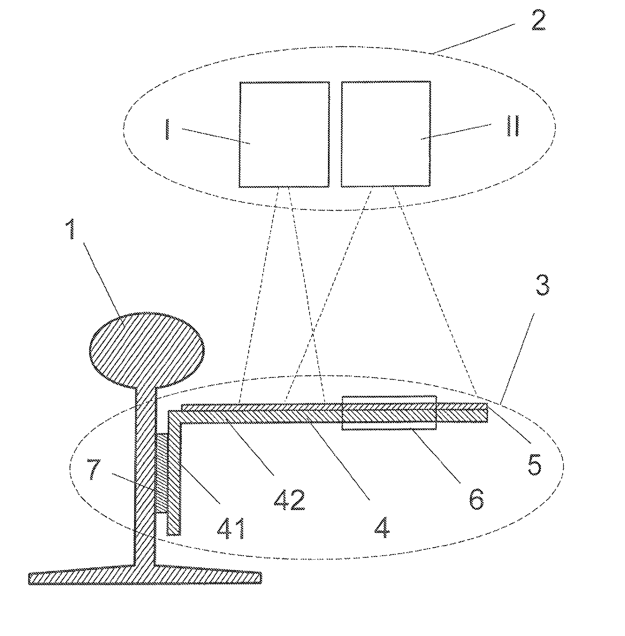
[0043]As is shown schematically in FIG. 1, the basic arrangement according to the invention comprises a measuring point 3 which is detachably arranged at a rail 1 (shown in a conventionalized manner as a Vignoles rail). A sensor unit 2 fastened to a work machine 8 is guided ove...


PUM

PropertyMeasurementUnit
distanceaaaaaaaaaa
diameteraaaaaaaaaa
lengthsaaaaaaaaaa

Abstract

An arrangement for marking and measuring sections of railroad track, which allows track sections which are susceptible to wear to be determined reliably and accurately. A sensor unit is provided for detecting measuring points, and has at least two independent detector units measuring in a non-contacting manner, based on a first optical sensor having spectrally selective sensitivity and a second identification detector. The measuring points, as angle elements, are detachably fastened to the rail and are provided at a horizontally oriented leg with a coating emitting in a narrow spectral band and with an identification value carrier for the identification detector. The sensor unit is so arranged at a device which can travel on tracks that the independent detector units are guided parallel to the rail in the same direction over the measuring points with the movement of the device which can travel on tracks.

Description

[0001]The present application claims priority from German Patent Application Nos. DE 10 2011 017 134.7 filed on Apr. 10, 2011, the disclosure of which is incorporated herein by reference in its entirety.BACKGROUND OF THE INVENTION[0002]1. Field of the Invention[0003]The invention is directed to an arrangement for marking and measuring sections of track for the purpose of maintaining railroad tracks, particularly in the area of switches, crossovers, curves, and other sections of track that are susceptible to wear.[0004]2. Description of Related Art[0005]Measurements of track for determining maintenance areas are performed in a variety of ways in the art through optical, capacitive, and eddy current measurements. In this connection, automated measurement by measuring trains is usually not sufficiently precise for wear-critical areas to directly control exact work by work machinery (grinding machines or tamping machines). Therefore, there is a need for performing exact in situ measurem...

Claims


Application Information

Patent Timeline
Patent Type & Authority Patents(United States)
IPC IPC(8): G01N21/00G01N21/55
CPCE01B35/00G01N21/00B61K9/08G01N21/55B61L23/045B61L23/047B61L23/048
Inventor SCHERF, WILFRIEDLUDDENEIT, MICHAEL
Owner SCHERF WILFRIED
Why Eureka
Try Eureka