Ambient noise removal device

a technology for removing devices and ambient noise, which is applied in the direction of active noise control, instruments, electrical transducers, etc., can solve the problems of increasing difficult to realize, and the noise signal detected by the microphone cannot be input to the audio apparatus, so as to reduce the size of the speaker casing, detect and remove ambient noise, and reduce the cost

Inactive Publication Date: 2013-08-20
YAMAHA CORP
View PDF9 Cites 6 Cited by
  • Summary
  • Abstract
  • Description
  • Claims
  • Application Information

AI Technical Summary

Benefits of technology

[0005]In view of the foregoing, it is an object of the present invention to provide an improved ambient noise removal device which can detect and remove ambient noise sound at reduced cost and without increasing a size of a casing of a speaker.
[0007]The present invention arranged in the aforementioned manner detects the ambient noise of the speaker by detecting the electromotive force produced in the speaker and thereby cancels the ambient noise. Thus, the present invention can reduce the number of a microphone that was heretofore used for canceling ambient noise.
[0012]The present invention arranged in the aforementioned manner detects the ambient noise of the speaker by detecting the electromotive force produced in the speaker by the ambient noise and thereby cancels the ambient noise. Thus, the present invention can eliminate a need for a microphone for detecting ambient noise and thus can avoid cost increase and prevent size increase of a casing of the speaker. Particularly, where the speaker is a headphone speaker, an ordinary- or conventional-type interface can be used as the interface for connecting the headphone to the sound signal output section, and thus, the ambient noise removal device of the present invention can achieve an enhanced convenience.

Problems solved by technology

However, in cases where a microphone is used to detect ambient noise sound as in the aforementioned conventionally-known techniques, a microphone has to be mounted for each of left and right headphone casings, which would undesirably increase cost and increase the size of the headphone casings.
Particularly, with the technique disclosed in Patent Literature 2, two microphones have to be mounted for each of the left and right headphone casings, which tends to difficult to realize if the headphones are small-size headphones, like a canal type.
Where a sound signal is stereo signals, the interface generally has three terminals, and thus, if the headphone has a microphone mounted thereon, a noise signal detected by the microphone cannot be input to the audio apparatus.
Therefore, in cases where a process for removing a noise signal detected by a microphone of a headphone is performed by such an audio apparatus, an ordinary- or conventional-type interface cannot be used as-is, so that it is necessary to provide a dedicated interface or a separate conversion device for converting the conventional-type interface.

Method used


Image

  • Ambient noise removal device
  • Ambient noise removal device
  • Ambient noise removal device

Examples


first embodiment

[First Embodiment of the Sound Signal Processing Section]

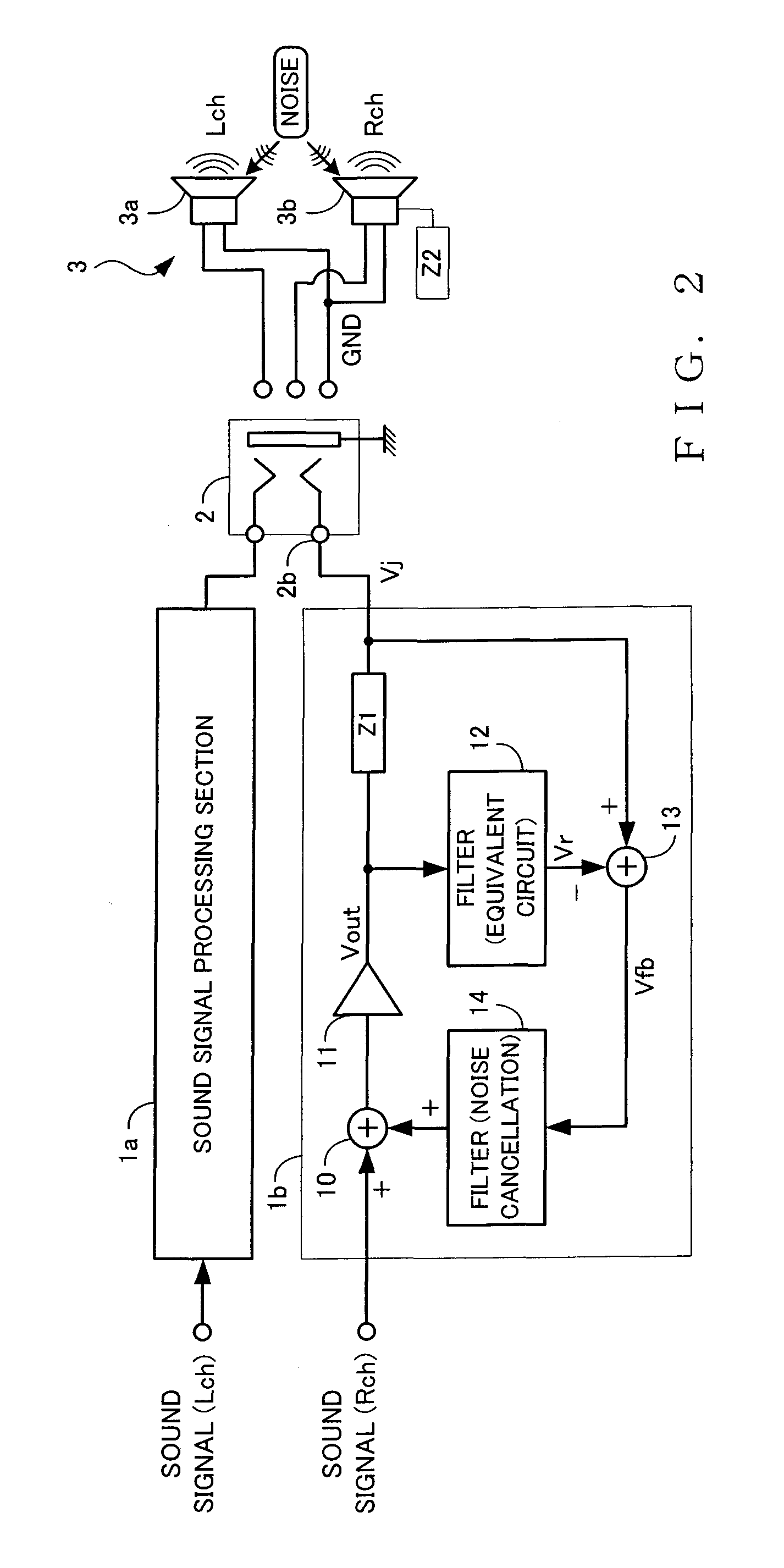
[0030]FIG. 2 is a block diagram showing the first embodiment of the sound signal processing section 1b. As shown, the sound signal processing section 1b includes adders 10 and 13, an amplifier 11, a predetermined output impedance Z1, and filters 12 and 14 each constructed of an analog circuit. In the sound signal processing section 1b of FIG. 2, a sound signal is input to and amplified by the amplifier 11. The sound signal Vout thus amplified by the amplifier 11 is output through the predetermined output impedance Z1 to thereby drive the speaker 3b.

[0031]A voltage Vj at the jack terminal 2b with no noise present around the speaker 3b takes a value corresponding to a voltage divided by the output impedance Z1 and a load impedance Z2 of the speaker 3b, which therefore can be expressed as

Vj=Vout*Z2 / (Z1+Z2)

[0032]The sound signal processing section 1b of FIG. 2 also includes the filter 12 that is an equivalent circuit of the speak...

third embodiment

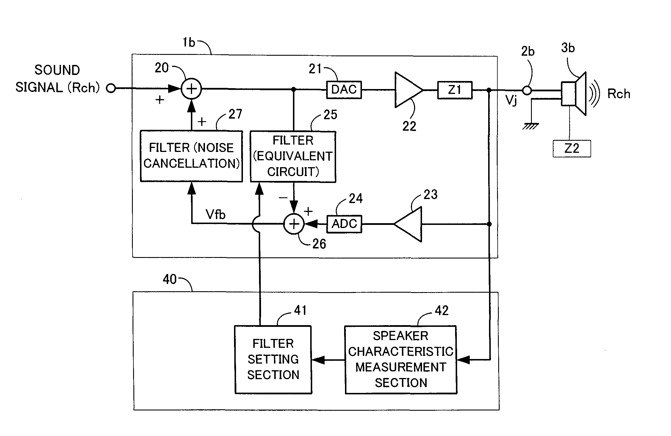
[Third Embodiment of the Sound Signal Processing Section]

[0043]The following describe a third embodiment of the sound signal processing section 1b. In the above-described first and second embodiments, the equivalent circuit, including the equivalent impedance of the speaker 3b, comprises an analog filter. By contrast, the third embodiment is characterized in that the equivalent circuit, including the equivalent impedance of the speaker 3b, comprises a digital filter implemented, for example, by a DSP so that the circuit can be constructed more simply and implemented and mounted more easily than the one constructed of an analog filter.

[0044]FIG. 4 is a block diagram showing the third embodiment of the sound signal processing section 1b. As shown, the sound signal processing section 1b includes adders 20 and 26, a D / A converter 21, amplifiers 22 and 23, a predetermined output impedance Z1, an A / D converter 24, and digital filters 25 and 27. Each sound signal input to the sound signal ...

application example 1

[0066]FIG. 8 is a block diagram showing application example 1 applied to the sound signal processing section 1b. As shown, this sound signal processing section 1b is constructed for connection with the headphone 3 that includes, in a headphone casing 8 for attachment to an ear of the user, the speaker 3b and a microphone 9 for detecting ambient noise sound. Therefore, unlike in the above-described embodiments, a conventional three-terminal interface cannot be used as the interface 2 for connecting the headphone 3 to the audio apparatus.

[0067]Further, in the sound signal processing section 1b of FIG. 8, an adaptive filter (ADF) 51 generates a noise cancellation signal on the basis of a noise signal detected by the microphone 9. The adaptive filter 51 is a filter that self-adapts its transfer function to an optimal one by changing its characteristics. The adder 10 adds the noise cancellation signal, output from the adaptive filter 51, to the sound signal by the adder 10, to generate a...


PUM


Abstract

An ambient noise removal device includes: a sound signal output section that outputs a sound signal to thereby drive a speaker; a noise detection section that detects an electromotive force produced in the speaker by ambient noise; and a noise cancellation section that generates, on the basis of the electromotive force, a signal of an opposite phase from the ambient noise and adds the generated signal to the sound signal to thereby cancel the ambient noise.

Description

BACKGROUND[0001]The present invention relates to ambient noise removal device for detecting and canceling or removing noise sound around a headphone speaker or the like.[0002]Heretofore, there have been proposed various techniques which, when a sound signal is to be reproductively output via a headphone speaker, reproduce the sound signal after canceling ambient noise (sound) around the speaker. Japanese Patent Application Laid-open Publication No. 2007-28354 (hereinafter referred to as “Patent Literature 1”) discloses a technique in accordance with which a microphone for detecting ambient noise sound is provided outside a casing of a headphone and noise sound is canceled by a headphone speaker being driven with a signal of an opposite phase from the noise signal detected by the microphone. Further, Japanese Patent No. 2822224 (hereinafter referred to as “Patent Literature 2”) discloses a technique in accordance with which a first microphone for detecting ambient noise sound is prov...

Claims


Application Information

Patent Timeline
Patent Type & Authority Patents(United States)
IPC IPC(8): H04R29/00H04B15/00H04R1/10
CPCG10K11/178G10K2210/3055H04B15/00G10K11/17875G10K11/17854G10K11/17885G10K11/1785
Inventor MORISHIMA, MORITONORIMATSU, TAKASHI
Owner YAMAHA CORP
Why Eureka
Try Eureka