Intake system for a vehicle

a technology for air intake and vehicles, which is applied in the direction of machines/engines, combustion-air/fuel-air treatment, and separation processes, etc., can solve the problems of low flow rate, low flow rate, and insufficient shape of the intake tube, so as to reduce the separation, increase the flow rate, and uniform flow distribution

Inactive Publication Date: 2013-08-27
HONDA MOTOR CO LTD
View PDF8 Cites 7 Cited by
  • Summary
  • Abstract
  • Description
  • Claims
  • Application Information

AI Technical Summary

Benefits of technology

[0005]In accordance with one aspect, an intake tube for an air intake system of a vehicle is provided. The air intake system is located upstream of an intake manifold and includes an intake enclosure and an air precleaner. The intake tube directs a flow of air from the intake enclosure to the air precleaner. The intake tube comprises a first end section, a second end section and a curved section. The first end section is connected to the intake enclosure and has a first longitudinal axis. An inner surface of the first end section defines a first section air passage. The second end section is connected to the air precleaner and has a second longitudinal axis. The inner surface of the second end section defines a second section air passage. The curved section is located between the first and second end sections. The curved section has a third longitudinal axis. An inner surface of the curved section defines a curved air passage. The curved section includes a compressed portion having a minor dimension and a major dimension. The major dimension is greater than the minor dimension so that the flow of air through the curved air passage has minimal separation which increases flow rate into the air precleaner.
[0006]In accordance with another aspect, an air intake system of a vehicle comprises an intake enclosure, an air precleaner and an air intake tube. The intake enclosure has an inlet in communication with atmosphere and an outlet. The air precleaner has an inlet and an outlet in communication with an associated intake manifold located downstream of the air precleaner. The intake tube fluidly connects the intake enclosure and the air precleaner. The intake tube includes an inlet section, an outlet section and a curved section. The inlet section is in communication with the intake enclosure outlet. The inlet section defines a first axial centerline. The cross-sectional area along any plane taken generally normal to the first axial centerline is approximately constant. The outlet section is in communication with the air precleaner inlet. The outlet section defines a second axial centerline. The cross-sectional area along any plane taken generally normal to the second axial centerline is approximately constant. The curved section is located between the inlet and outlet sections. The curved section defines a third axial centerline. The curved section is squeezed such that the curved section includes a minor diameter and a major diameter. The cross-sectional area along any plane taken generally normal to the third axial centerline is approximately constant. The flow of air through the inlet tube has minimal separation which increases flow rate and the air entering the air cleaner has a more uniform flow distribution.
[0007]In accordance with yet another aspect, a method of preventing flow loss in an air intake system of a vehicle is provided. An intake enclosure is provided for collecting air to be delivered to an intake manifold of the vehicle. An air precleaner is provided downstream of the intake enclosure and is in communication with the intake enclosure. The air precleaner filters the flow of air into the intake manifold. An intake tube is disposed between and fluidly connects the intake enclosure and the air precleaner. The intake tube includes a curved section. The curved section is compressed to prevent airflow separation through the curved section. An approximately constant cross-sectional area is maintained along any plane taken generally normal to a longitudinal axis defined by the curved section so that the air entering the precleaner has a uniform flow distribution.

Problems solved by technology

As such, the intake tube often does not have a shape sufficient to inhibit the occurrence of a turbulent flow to enable air taken in through the intake port to be supplied smoothly to the air precleaner.
This design can cause airflow separation in the curved section which leads to flow loss and an overall lower flow rate.

Method used


Image

  • Intake system for a vehicle
  • Intake system for a vehicle
  • Intake system for a vehicle

Examples


Embodiment Construction

[0017]It should, of course, be understood that the description and drawings herein are merely illustrative and that various modifications and changes can be made in the structures disclosed without departing from the present disclosure. It will also be appreciated that the various identified components of the air intake system disclosed herein are merely terms of art that may vary from one manufacturer to another and should not be deemed to limit the present disclosure. All references to direction and position, unless otherwise indicated, refer to the orientation of the air intake system illustrated in the drawings and should not be construed as limiting the claims appended hereto.

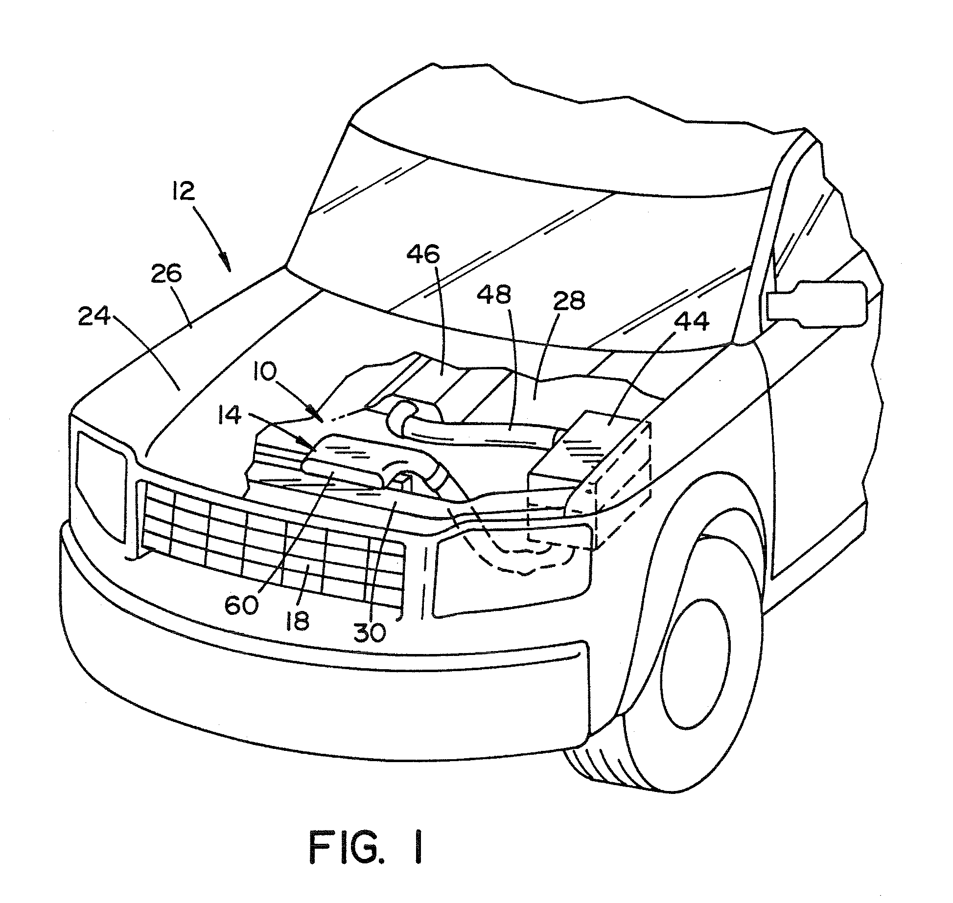
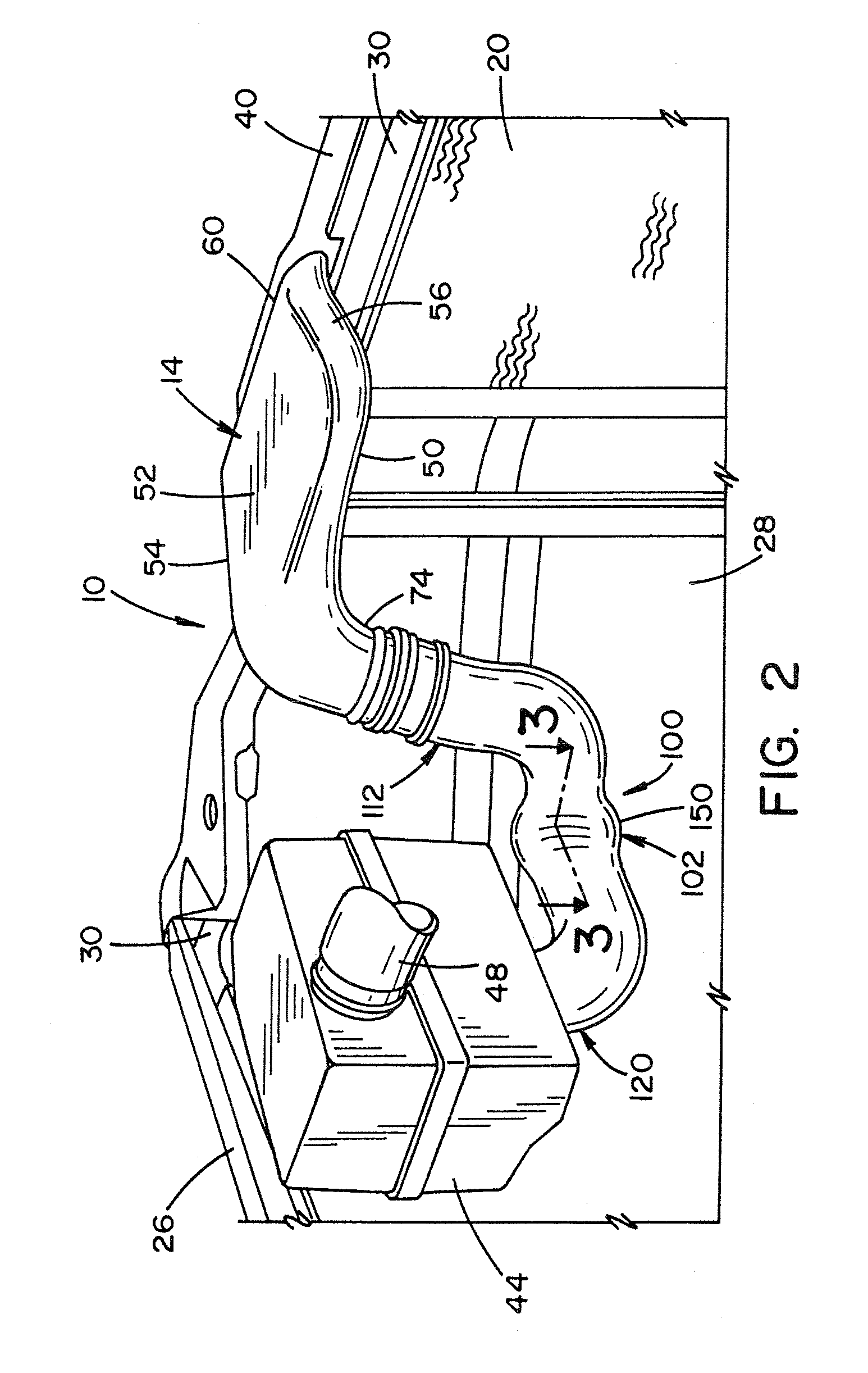
[0018]Referring now to the drawings, wherein like numerals refer to like parts throughout the several views, FIGS. 1 and 2 illustrate an air intake system 10 according to the present disclosure as part of a vehicle 12. As shown, the air intake system 10 generally includes an air intake enclosure 14 dispose...


PUM

PropertyMeasurementUnit
flow rateaaaaaaaaaa
areaaaaaaaaaaa
cross-sectional areaaaaaaaaaaa

Abstract

An intake tube for an air intake system of a vehicle is provided. The air intake system is located upstream of an intake manifold and includes an intake enclosure and an air precleaner. The intake tube directs a flow of air from the intake enclosure to the air precleaner. The intake tube comprises a first end section, a second end section and a curved section. The first end section is connected to the intake enclosure and has a first longitudinal axis. An inner surface of the first end section defines a first section air passage. The second end section is connected to the air precleaner and has a second longitudinal axis. The inner surface of the second end section defines a second section air passage. The curved section is located between the first and second end sections. The curved section has a third longitudinal axis. An inner surface of the curved section defines a curved air passage. The curved section includes a compressed portion having a minor dimension and a major dimension. The major dimension is greater than the minor dimension so that the flow of air through the curved air passage has minimal separation which increases flow rate into the air precleaner.

Description

[0001]This application claims the benefit of provisional patent application Ser. No. 61 / 158,787, filed Mar. 10, 2009, which is incorporated by reference in its entirety herein.BACKGROUND[0002]The present disclosure generally relates to a vehicle air intake system. More particularly, the present disclosure is directed to an improved air intake tube for an air intake system.[0003]Air intake systems provide necessary air to internal combustion engines to aid in the combustion process. Conventional intake systems either draw air from inside the engine compartment, or they draw air from outside the vehicle via an exterior intake port. The intake port is in communication with an intake tube or duct which directs air into an air precleaner. From the air cleaner, another intake tube or duct can be used to direct air to the vehicle's engine, specifically the engine's intake manifold.[0004]Because the intake system must fit within the compact engine compartments of contemporary vehicles, the ...

Claims


Application Information

Patent Timeline
Patent Type & Authority Patents(United States)
IPC IPC(8): F02M35/10
CPCF02M35/10118
Inventor SILVANO, PETER
Owner HONDA MOTOR CO LTD
Why Eureka
Try Eureka