Arrangement for determining a revolution rate and direction of rotation of a rotating component

a technology of rotating components and rotation rates, applied in the direction of electric/magnetic devices, instruments, transportation and packaging, etc., can solve the problems of inability to determine the inability to use revolution rate sensors with screw mountings, and the inability to accurately measure the direction of rotation, so as to avoid the disadvantages of conventional techniques

Active Publication Date: 2017-09-19
MAN TRUCK & BUS AG
View PDF18 Cites 1 Cited by
  • Summary
  • Abstract
  • Description
  • Claims
  • Application Information

AI Technical Summary

Benefits of technology

[0009]It is thus an object of the invention to provide an improved arrangement, in particular an improved rotation sensor device, for contactlessly determining a revolution rate and a direction of rotation of a component that rotates during its operation, with which the disadvantages of conventional techniques can be avoided. An object of the invention is in particular to provide a revolution rate sensor with which a revolution rate and a direction of rotation of a rotating component can be determined and that can be mounted rapidly and that does not require complex calibration or adjustment.
[0013]The provision according to the invention of at least three magnetic field sensors gives the particular advantage that regardless of the installation position of the sensor, i.e., the rotary position in the screwed-in state, there are always at least two magnetic field sensors at a different distance from the edge of the nearest protrusion, so that besides the determination of the angular rate of rotation, a determination of the direction of rotation is always possible—regardless of the angular position in which the sensor device is mounted. For this reason it is not necessary, when screwing in the sensor device, to pay attention to how the magnetic field sensors are oriented in the final position. As a result, the above aspect of the invention enables rapid assembly and mounting-related measurement errors to be avoided. Further, as a result of the distance of the magnetic field sensors that are farthest apart being less than or equal to a width of the grooves or tooth gaps, it is ensured that the change in the magnetic field strength recorded by different sensors is produced by the rotating component from the same edge. This enables reliable measurement of the angular rate of rotation of the shaft and the direction of rotation.
[0014]A particularly preferred exemplary embodiment provides that the magnetic field detecting device is formed by three magnetic field sensors that are disposed in the form of a triangle. In this case the lengths of the sides of the triangle are less than or equal to a width of the grooves or tooth gaps. The arrangement in the form of an equilateral triangle is particularly advantageous here. The arrangement in the form of an equilateral triangle enables a simplified analysis and computer processing of the detected magnetic field signals. Further, as a result it is ensured that in any rotary position the two magnetic field sensors that are farthest apart when viewed in the direction of rotation have a certain minimum separation from each other, which is advantageous for the detection of very high frequencies.
[0016]This ensures that in any installation position those two magnetic field sensors between which the time difference of the change in magnetic field produced by the edge of a protrusion is greatest are used for measurement, which improves the measurement accuracy. The analyzer is preferably in the form of part of the internal analysis electronics of the sensor device, but can also be implemented as an external analyzer.

Problems solved by technology

If, however, a rotation sensor is installed such that a stationary tooth is opposite both Hall elements at the same time, i.e., both Hall elements are at the same distance from the edge of the next tooth, then the total magnetic field strength on the two Hall elements is the same at any measurement point in time, and a direction of rotation can no longer be determined.
This problem can in particular occur with revolution rate sensors with screw mountings.
If the rotary position of the sensor in the screwed-in position is such that the two Hall elements are essentially at the same distance from the edge of the next tooth, the direction of rotation cannot be determined or measurement inaccuracies can occur if the difference in distance is too small or is unknown.
With such sensors it must be ensured during installation that the two Hall elements are correctly aligned in the final position, therefore a time-consuming readjustment may be necessary.
This does enable incorrect alignments to be corrected, but this is time-consuming, is liable to errors and requires suitably trained skilled staff during the installation.

Method used


Image

  • Arrangement for determining a revolution rate and direction of rotation of a rotating component
  • Arrangement for determining a revolution rate and direction of rotation of a rotating component
  • Arrangement for determining a revolution rate and direction of rotation of a rotating component

Examples


Embodiment Construction

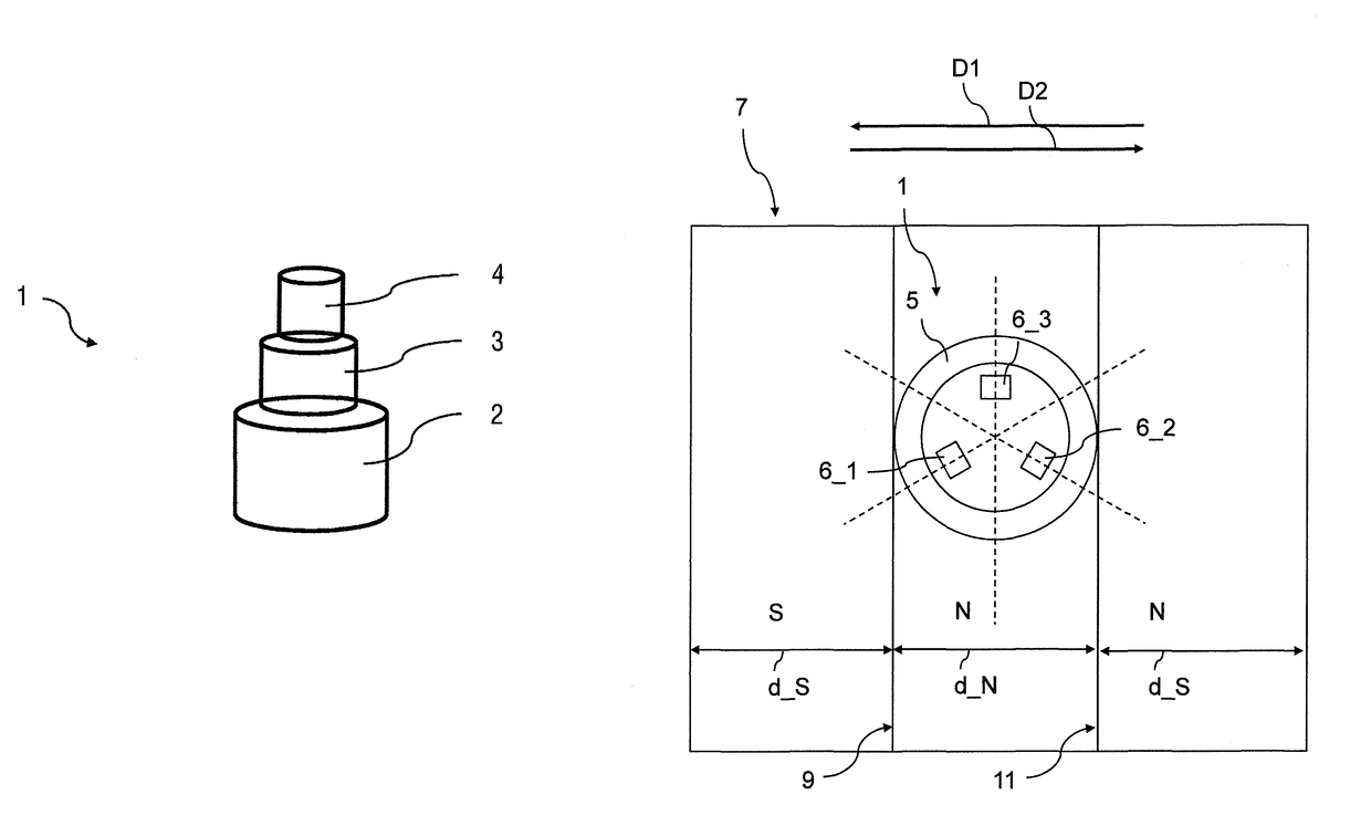
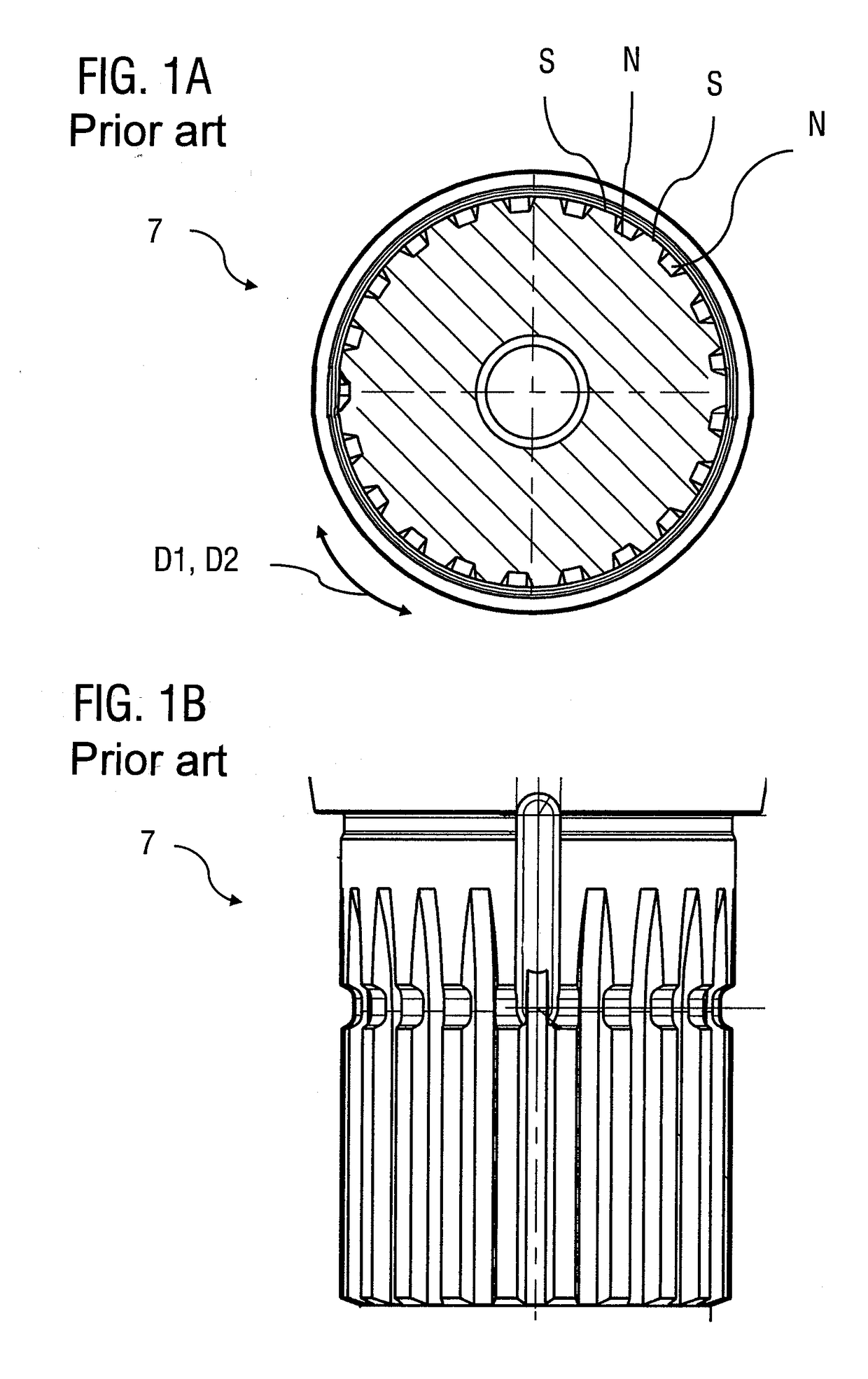
[0031]FIGS. 1A and 1B show a known shaft 7 made of a ferromagnetic material as an example of a component that rotates during its operation, the angular rate of rotation, acceleration and direction of rotation of which are intended to be measured by a sensor device. The shaft comprises a regular circumferential structure of grooves N and webs S. All the webs S have the same width as one another, and all the grooves N have the same width as one another, but the width of the grooves can be different from the width of the webs. The two possible directions of rotation D1 and D2 of the shaft 7 are indicated with the double arrow designated by D1 and D2.

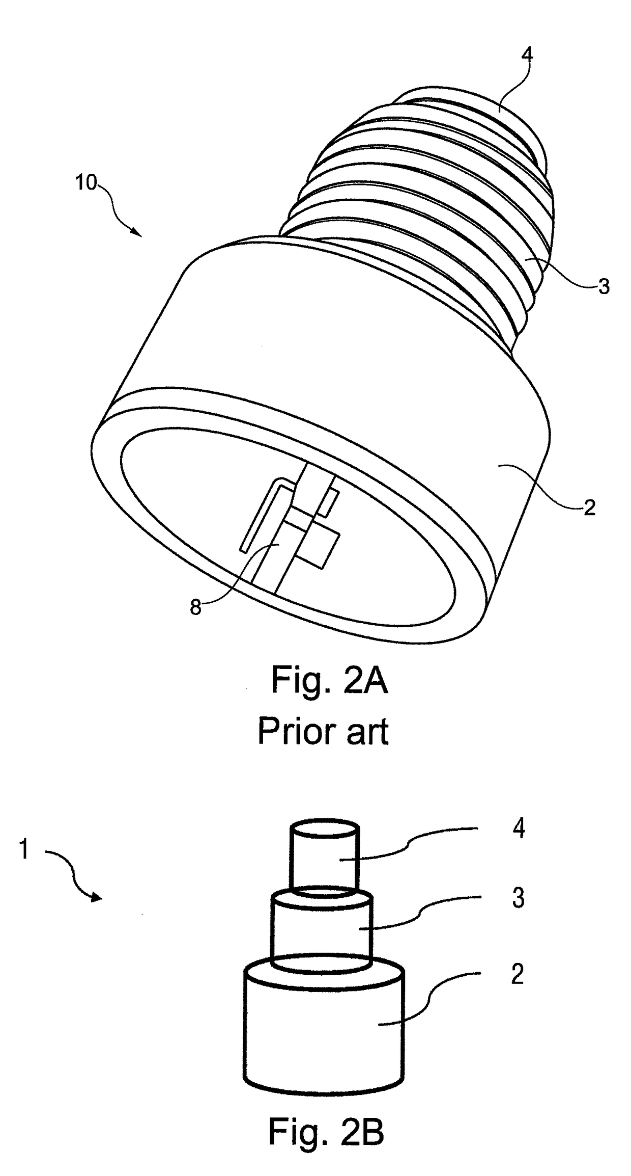
[0032]FIG. 2A shows schematically in a perspective view the design of a revolution rate sensor 10 that is known from the prior art. The known revolution rate sensor is implemented as a screw-in revolution rate sensor and comprises for this purpose a neck segment 3 with an external thread. The sensor is screwed into a corresponding threaded ...


PUM


Abstract

A sensor device for contactlessly determining a revolution rate and a direction of rotation of a component that rotates during operation of the component, the component having, on at least one peripheral region, a circumferential structure of web-shaped or tooth-shaped radial protrusions and interposed grooves or tooth gaps includes: a threaded segment configured to positionally fix an arrangement of the sensor device so that the circumferential structure of the component is movable past the sensor device; a magnetic field generating device; and a magnetic field detecting device having at least three magnetic field sensors that are not arranged in alignment along a line. A distance between the magnetic field sensors that are the farthest apart from each other is less than or equal to a width of the grooves or tooth gaps of the component.

Description

BACKGROUND OF THE INVENTION[0001]1. Field of the Invention[0002]The invention relates to an arrangement for contactlessly determining a revolution rate and direction of rotation of a component that rotates during its operation, in particular a magnetizable shaft of a motor vehicle.[0003]2. Related Art[0004]Different revolution rate sensors for determining the revolution rate of a component that rotates during its operation are known from the prior art. Such revolution rate sensors are, for example, used for detecting a revolution rate and a direction of rotation of a gear wheel or a transmission shaft in a gearbox of a motor vehicle.[0005]For contactlessly detecting a revolution rate, revolution rate sensors are usually used that are equipped with a magnetic field sensor (for example a Hall sensor). In such sensors, a magnetic field, which changes when a tooth of the gear wheel passes, is generated by a magnet in the vicinity of the Hall sensor. During this the Hall sensor first det...

Claims


Application Information

Patent Timeline
Patent Type & Authority Patents(United States)
IPC IPC(8): G01B7/30G01D5/14G01P3/488G01P13/04B62D63/04G01B7/14G01R33/07G01P3/44
CPCG01P13/045G01P3/44B62D63/04G01D5/145G01P3/488G01P3/487
Inventor KOCK, PETERBUCKLERS, GUNTERSTEINBERG, CHRISTOPH
Owner MAN TRUCK & BUS AG
Why Eureka
Try Eureka