Manufacture of a wind turbine blade

a wind turbine and blade technology, applied in the field of wind turbine blade manufacturing, can solve the problems of insufficient adhesive in the bondline between the blade shell and the mounting flange of the shear web, difficult to detect using non-destructive testing methods, and difficulty in controlling the compression of adhesive, so as to minimize the number of steps in the manufacturing process of the flange. , the effect of constant cross-section

Active Publication Date: 2021-09-28
VESTAS WIND SYST AS
View PDF58 Cites 1 Cited by
  • Summary
  • Abstract
  • Description
  • Claims
  • Application Information

AI Technical Summary

Benefits of technology

[0008]The protruding features may prevent the bonding surface of the flange from approaching too close to the inner surface of a wind turbine blade to which the flange is to be bonded. In this regard, the protruding features may function as depth stops and may ensure that a minimum separation is maintained between the bonding surface and the inner surface of the wind turbine blade.
[0009]If adhesive is provided in the region between the bonding surface and the inner surface of the wind turbine blade, then the protruding features may prevent too much adhesive from being squeezed out of that region. Therefore, the protruding features may ensure a minimum thickness of adhesive is present in the bondline between the bonding surface and the inner surface of the wind turbine blade and hence ensure a high-quality bond.
[0011]The one or more protruding features may comprise one or more longitudinally extending ridges. The one or more protruding features may comprise a plurality of ridges that are mutually spaced apart in a lateral direction across the width of the flange. This advantageously ensures the stability of the flange when arranged against the inner surface of a wind turbine blade. A minimum thickness of adhesive is therefore ensured across the width of the flange.
[0012]The flange may comprise first and second peripheral ridges that are respectively laterally spaced inwardly of first and second longitudinal edge regions of the flange. The flange may comprise a central ridge located substantially centrally between first and second longitudinal edges of the flange. The central ridge may be configured to support the central portion of the flange and prevent the flange from flexing in the centre and forming a kissing bond.
[0016]The one or more protruding features may be formed integrally with the flange. This advantageously minimizes the number of steps in the flange manufacturing process. In other embodiments, separate protruding features may be attached to the bonding surface of the flange.
[0018]The flange may comprise reinforcing fibres in a cured resin matrix. The reinforcing fibres may be any suitable material, for example glass or carbon, and the resin matrix may comprise epoxy or other suitable resin. The flange may comprise fibres in any orientation. The protruding features may comprise unidirectional fibres. Use of unidirectional fibres for the protruding features advantageously simplifies the pultrusion process. A portion of the flange may comprise fibres oriented in more than one direction. For example, the remainder of the flange may comprise fibres predominantly arranged in three directions. This allows for efficient transfer of loads from the shear web to the surface to which the flange is to be bonded.

Problems solved by technology

It can be difficult to control the compression of the adhesive and in some cases the adhesive may be compressed too far so that too much adhesive is squeezed out of the bondlines leaving insufficient adhesive in the bondlines between the blade shell and the mounting flanges of the shear webs.
With insufficient adhesive in the bondlines, the mounting flanges of the shear web may have a tendency to flex against the blade shell resulting in a so-called ‘kissing bond’, which may be difficult to detect using non-destructive testing methods.

Method used


Image

  • Manufacture of a wind turbine blade
  • Manufacture of a wind turbine blade
  • Manufacture of a wind turbine blade

Examples


Embodiment Construction

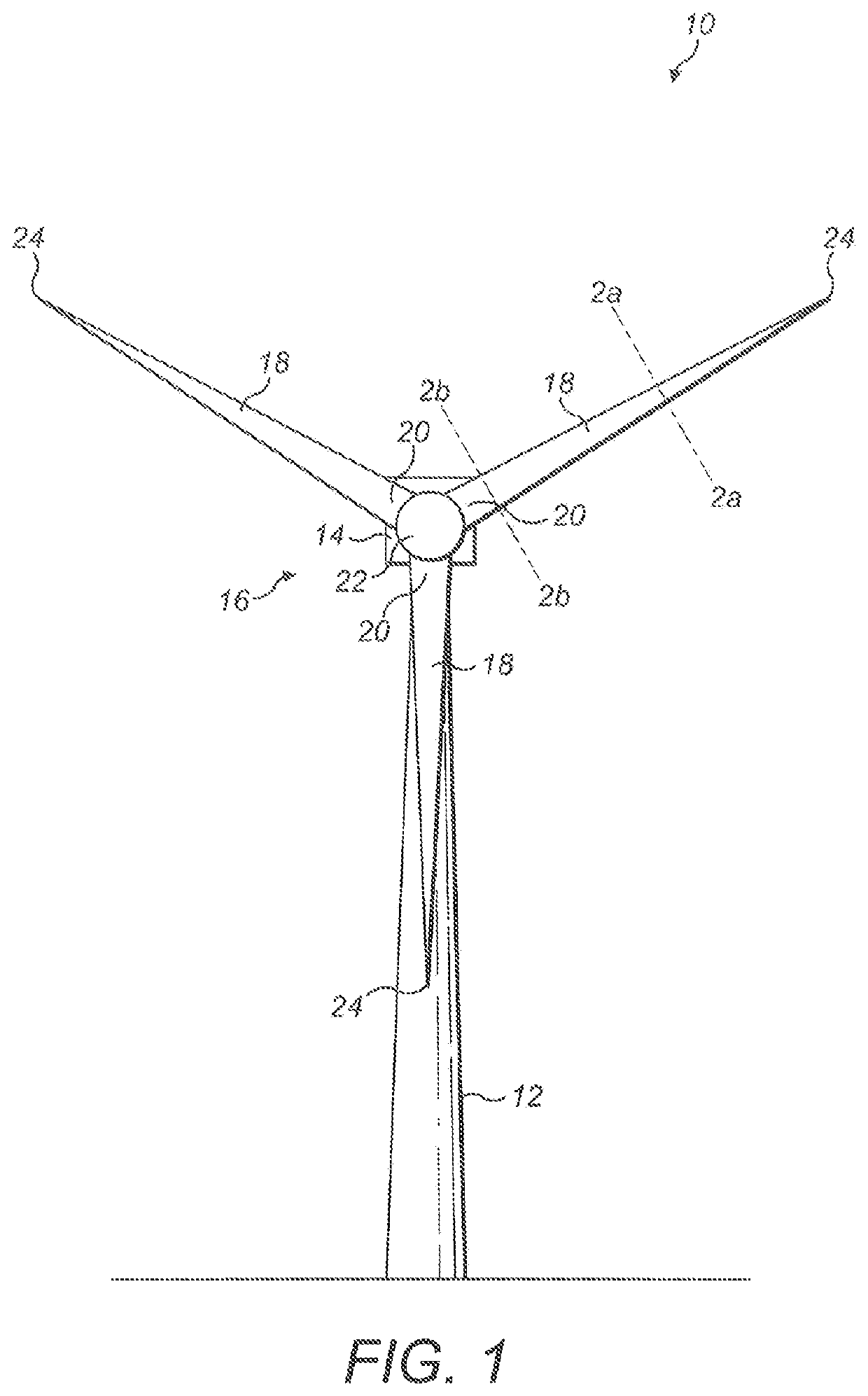
[0035]Referring initially to FIG. 1, a wind turbine 10 according to an embodiment of the present invention is shown schematically. The wind turbine 10 comprises a tower 12 supporting a nacelle 14 to which a rotor 16 is mounted. The rotor 16 comprises a plurality of wind turbine blades 18 that extend radially from a root end 20, attached to a central hub 22, to a tip end 24. In this example, the rotor comprises three blades 18.

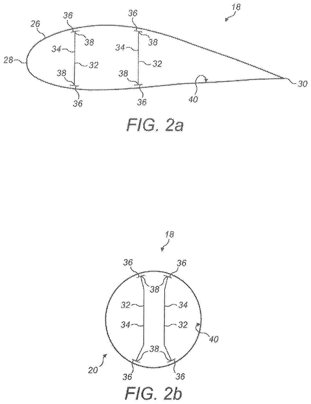
[0036]FIG. 2a shows a schematic cross-sectional view of an airfoil portion of a wind turbine blade 18 taken along the line 2a-2a in FIG. 1. The blade 18 may comprise a hollow shell 26 made up of two half-shells bonded together along the leading and trailing edges 28, 30 of the blade 18. Two shear webs 32 are located within the internal cavity of the blade 18. The shear webs 32 extend longitudinally along the length of the blade 18, transverse to the plane of the page.

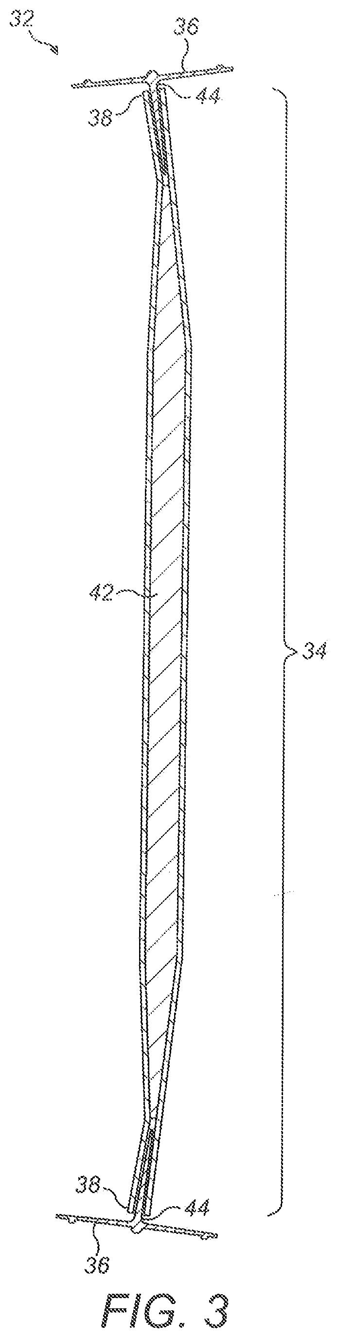
[0037]In this example, each shear web 32 comprises a central web element 34 with two mounting f...


PUM

PropertyMeasurementUnit
depthaaaaaaaaaa
lengthaaaaaaaaaa
widthaaaaaaaaaa

Abstract

A shear web flange (36) for a shear web (32) of a wind turbine blade (18) is described. The flange (36) extends longitudinally and comprises a bonding surface (50) for bonding to an inner surface of a wind turbine blade (18). One or more protruding features (52a, 52b) protrude from the bonding surface (50). A method of making such a shear web flange (36) is also described as are a shear web (32) for a wind turbine blade (18), a wind turbine blade (18) and a method of making a wind turbine blade (18).

Description

FIELD OF THE INVENTION[0001]The present invention relates generally to the manufacture of wind turbine blades, and more specifically to a shear web flange that improves the manufacture of wind turbine blades.BACKGROUND TO THE INVENTION[0002]Modern wind turbine blades typically comprise a hollow shell made up of two half-shells bonded together along leading and trailing edges of the blade. Two longitudinally-extending shear webs are typically provided inside the internal cavity of the blade. Each shear web comprises two longitudinally-extending mounting flanges that are bonded to opposed inner surfaces of the respective half-shells. As such, the shear webs bridge the two half-shells.[0003]The shear webs are load-bearing components that serve to strengthen and stiffen the blade. It is therefore important that a strong bond is achieved between the mounting flanges of the shear webs and the inner surfaces of the half-shells as the integrity of the blade is dependent on the quality of th...

Claims


Application Information

Patent Timeline
Patent Type & Authority Patents(United States)
IPC IPC(8): F03D1/06B29C70/52B29D99/00F03D13/10B29C65/48B29C65/00B29L31/08B29K63/00B29K307/04B29K309/08
CPCF03D1/0675B29C65/48B29C66/7212B29C70/52B29D99/0028F03D1/065F03D13/10B29K2063/00B29K2307/04B29K2309/08B29L2031/085F05B2230/24F05B2230/60F05B2240/2212F05B2240/301F05B2280/6003F05B2280/6013F05B2280/6015Y02E10/72Y02P70/50
Inventor HAWKINS, JASONFIELD, CRAIGWARDROPPER, STEVE
Owner VESTAS WIND SYST AS
Why Eureka
Try Eureka