Stress-relieved acrylic optical lenses and methods of manufacture by injection coining molding

Inactive Publication Date: 2005-01-11
FGX INT
View PDF3 Cites 2 Cited by
  • Summary
  • Abstract
  • Description
  • Claims
  • Application Information

AI Technical Summary

Benefits of technology

The present invention provides an improved method and process for injection-coining molding of positive and minus diopter lenses out of acrylic material, which are stress-relieved and able to pass a standardized impact resistance test. As used herein, the term “injection-coining” refers to injection mold processes wherein separation of the mold p

Problems solved by technology

However, polycarbonate lenses have the disadvantages of producing birefringence at the perimeter of the lens, and a tendency to yellow with age.
However, molded acrylic is more brittle than molded polycarbonate, due to its relatively low glass transition temperature, higher density and higher tensile strength.
Although magnifying, non-refractive, and positive diopter ophthalmic lenses have been molded out of acrylic, such lenses generally have molded-in stresses, produced by shearing of the material in the molding process, which make them brittle and not able to pass the standard drop ball impact test.
Discontinuity in the rate of flow of material into the mold cavity also causes shearing which produces birefringence in the molded lens.
Because of the extreme difference in cross-sectional thickness of the mold cavity, the molding m

Method used


Image

  • Stress-relieved acrylic optical lenses and methods of manufacture by injection coining molding
  • Stress-relieved acrylic optical lenses and methods of manufacture by injection coining molding
  • Stress-relieved acrylic optical lenses and methods of manufacture by injection coining molding

Examples


Embodiment Construction

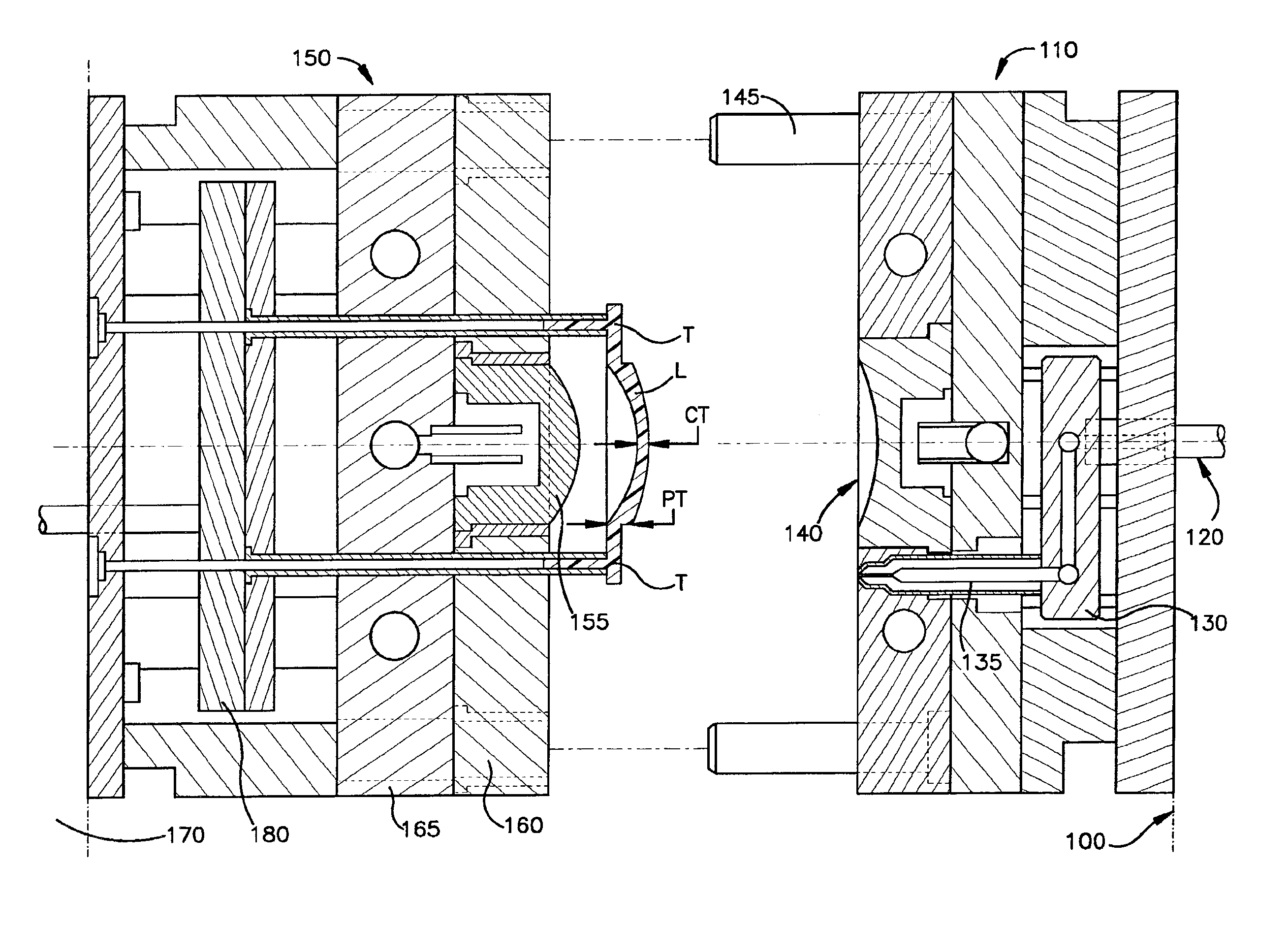
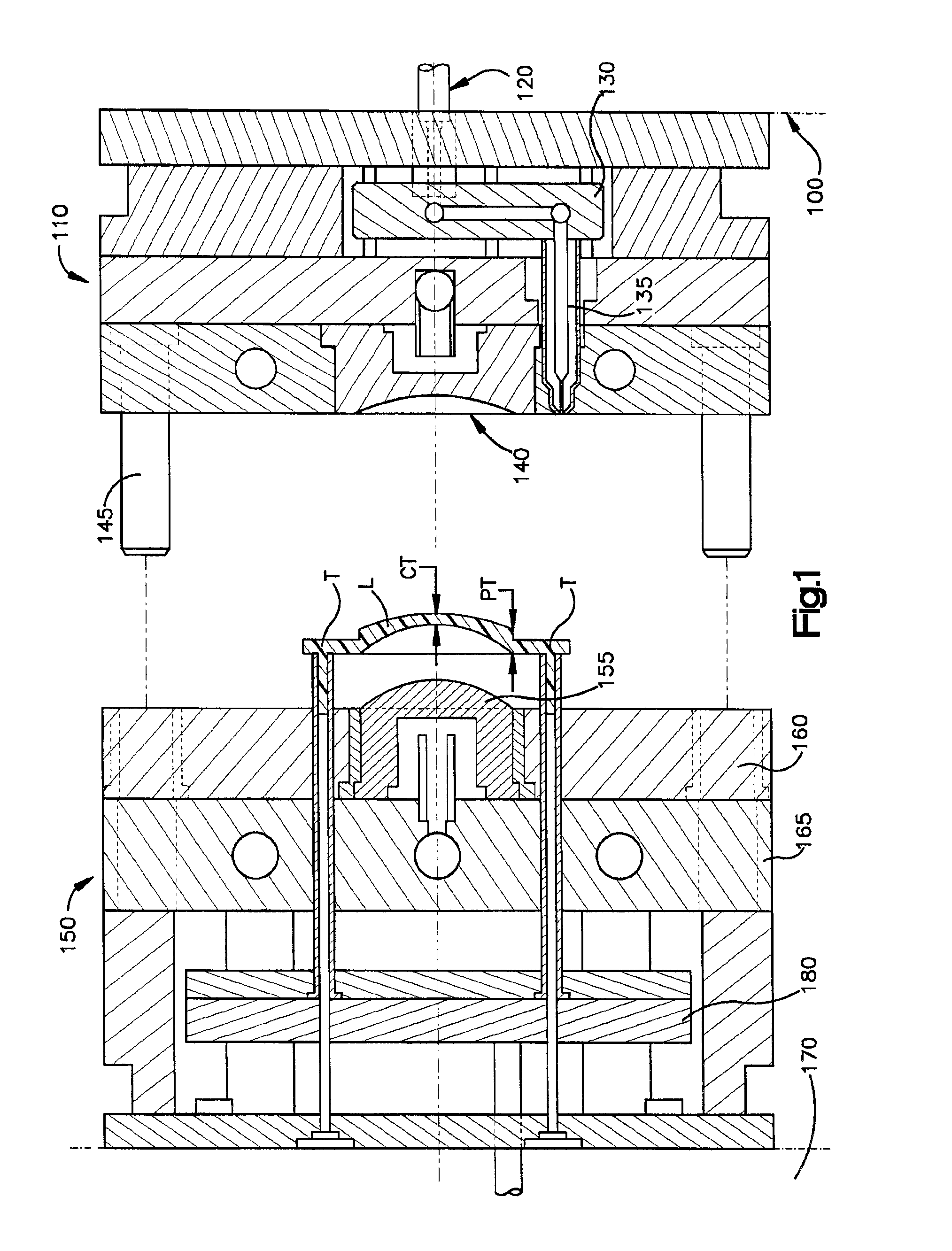
The methods of the present invention can be used in connection with different types of injection molds, including conventional two-plate or runnerless molds, and three-plate injection-coining molds. As used herein, the term “injection-coining” refers to the control of a moveable half or intermediate cavity plate of a mold assembly, relative to a stationary plate of the mold assembly, by which the moveable half or component or plate of the mold assembly is controlled to move the core plate to apply a coining stroke relative to the stationary half of the mold, to densify material within the mold cavity.

An injection-coining lens molding process of the invention is able to be carried out with a conventional two plate or “runnerless” mold, as depicted in FIG. 1, with a stationary A half 110 attached to a stationary platen 100 of an injection molding machine. A mold material injection screw (connected to a plasticating unit including an injection unit having a heated extruder barrel, hopp...


PUM

PropertyMeasurementUnit
Thicknessaaaaaaaaaa
Thicknessaaaaaaaaaa
Temperatureaaaaaaaaaa

Abstract

Stress-relieved molded acrylic opthalmic lenses, and injection-coining mold processes for molding stress-relieved plus and minus to high-minus diopter ophthalmic lenses of optically superior acrylic resin, able to pass standardized impact drop tests for use as eyeglass lenses, are described. The injection-coining processes use two-plate and three-plate mold assemblies. The cavity of a two plate runnerless mold is partially filled under partial tonnage, and the movable half of the mold controlled to coin and densify the acrylic resin under secondary or full tonnage, when a velocity-pressure changeover point is reached. In a process which employs a three-plate mold assembly, the lens mold cavities are partially filled under less than total clamp tonnage, with a cavity plate held by hydraulic pressure against a movable half of the mold. The mold assembly is then closed under full tonnage when a velocity-pressure changeover point is reached, collapsing the cavity plate a stationary platen, bringing the mold assembly to a total stack height. The processes produce impact resistant acrylic ophthalmic lenses which are stress-relieved and without weld lines, even in the high minus diopter range, with center thickness' as low as one millimeter, and edge thickness' up to ten millimeters.

Description

FIELD OF THE INVENTIONThe present invention pertains generally to the manufacture of objects by injection molding, such as lenses and, more particularly, to the molding of ophthalmic vision correction lenses with injection-coining molding processes.BACKGROUND OF THE INVENTIONVision correction and magnification lenses for eyeglasses were originally made of glass. More recently, lenses have been made from polycarbonate material molded in different types of injection molding processes. Polycarbonate lenses are much lighter than glass lenses of the same power, and are sufficiently strong to pass a standardized drop / breakage test, ANSI Z80.1-1995, in which a 0.56 ounce steel ball is dropped from a vertical height of 50 inches on to the center of the lens, even with a relatively thin center thickness in a range of approximately 1.0 to 1.5 mm. However, polycarbonate lenses have the disadvantages of producing birefringence at the perimeter of the lens, and a tendency to yellow with age.Acry...

Claims


Application Information

Patent Timeline
IPC IPC(8): B29C45/56B29D11/00B29C45/00
CPCB29C45/561B29D11/00192B29D11/00432B29D11/00413Y10S425/808B29L2011/0016
Inventor POPE, DARRELL
Owner FGX INT
Why Eureka
Try Eureka