Integrated multifunctional powered wheel system for aircraft

a multi-functional, powered wheel technology, applied in the direction of skis/runners, energy-saving operation measures, alighting gear, etc., can solve the problems of insufficient relief on the main braking system, inability to control the taxiing procedure entirely from the outside, and high additional weight in return for a relatively modest number of additional functions. , to achieve optimally boost the main undercarriage brake, the effect of improving the braking

Active Publication Date: 2013-08-27
AIRBUS SAS +1
View PDF26 Cites 16 Cited by
  • Summary
  • Abstract
  • Description
  • Claims
  • Application Information

AI Technical Summary

Benefits of technology

[0005]It may thus be an object of the invention to provide a device or a system by means of which wheels of an undercarriage of an aircraft may be driven; in addition the braking effect may be improved, and automatic, semi-automatic or manual taxiing may be facilitated, while the additional weight on board the aircraft may be kept as low as possible. It may be a further object of the invention to provide a device or a system that may be able to optimally boost the main undercarriage brakes so that the time period between two flights may be reduced.
[0009]Furthermore, the powered wheel system according to the invention is able, after landing and during the braking procedure, to boost the main undercarriage brakes by means of the motors. To this effect the control device obtains, for example, data relating to the aircraft weight, the state of the braking system, and the length and state of the runway from the aforesaid systems as well as from the braking system and steering system. Based on this data a kind of desired rotary speed in reverse may be calculated, which, for example if electric motors are used, results in a rotary frequency of the magnetic field. While the wheels continue to rotate in forward direction during the braking procedure, an anti-torque is however generated by the opposite rotary field of the electric motors, which anti-torque acts against the rotation of the wheels. In addition, in the calculation of the desired rotary speeds the state of the runway may be taken into account to the extent that no slip occurs as a result of excessive additional anti-torque.
[0011]To provide improved boosting of the main braking system after the braking procedure, the powered wheel system according to the invention is preferably also in a position to selectively decouple the motor or motors from the wheels to be driven, and to connect said motor or motors to fans that make it possible to cool down friction-based braking means. Consequently, the cooling-down time of the main brakes is reduced so that the aircraft may be more quickly readied for the next flight. In addition, decoupling of the motors from the wheels may be done without if the aircraft, for example, after landing moves to a predetermined parking position. However, when said parking position has been reached, decoupling the motors from the wheels will become necessary.

Problems solved by technology

The largest shared disadvantage relates to the relatively high additional weight in return for a relatively modest number of additional functions gained, which functions are not available to a conventional aircraft.
For example, the proposed systems do not make it possible to control the taxiing procedure entirely from the outside without the need to use the aircraft's own steering.
Nor is it possible, moreover, with the proposed devices and systems to achieve efficient boosting of the braking system, for, while a certain braking effect is achieved by the polarity reversal of the wheel motors or by other measures, the relief on the main braking systems is however not sufficient to stop heating of the main brakes to their operating temperature and the need for cooling on the ground so as to make it possible for the aircraft to take off again in the shortest possible period of time.

Method used


Image

  • Integrated multifunctional powered wheel system for aircraft
  • Integrated multifunctional powered wheel system for aircraft
  • Integrated multifunctional powered wheel system for aircraft

Examples


Embodiment Construction

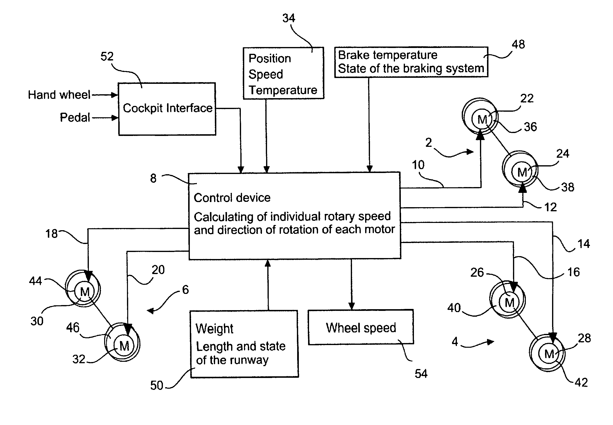
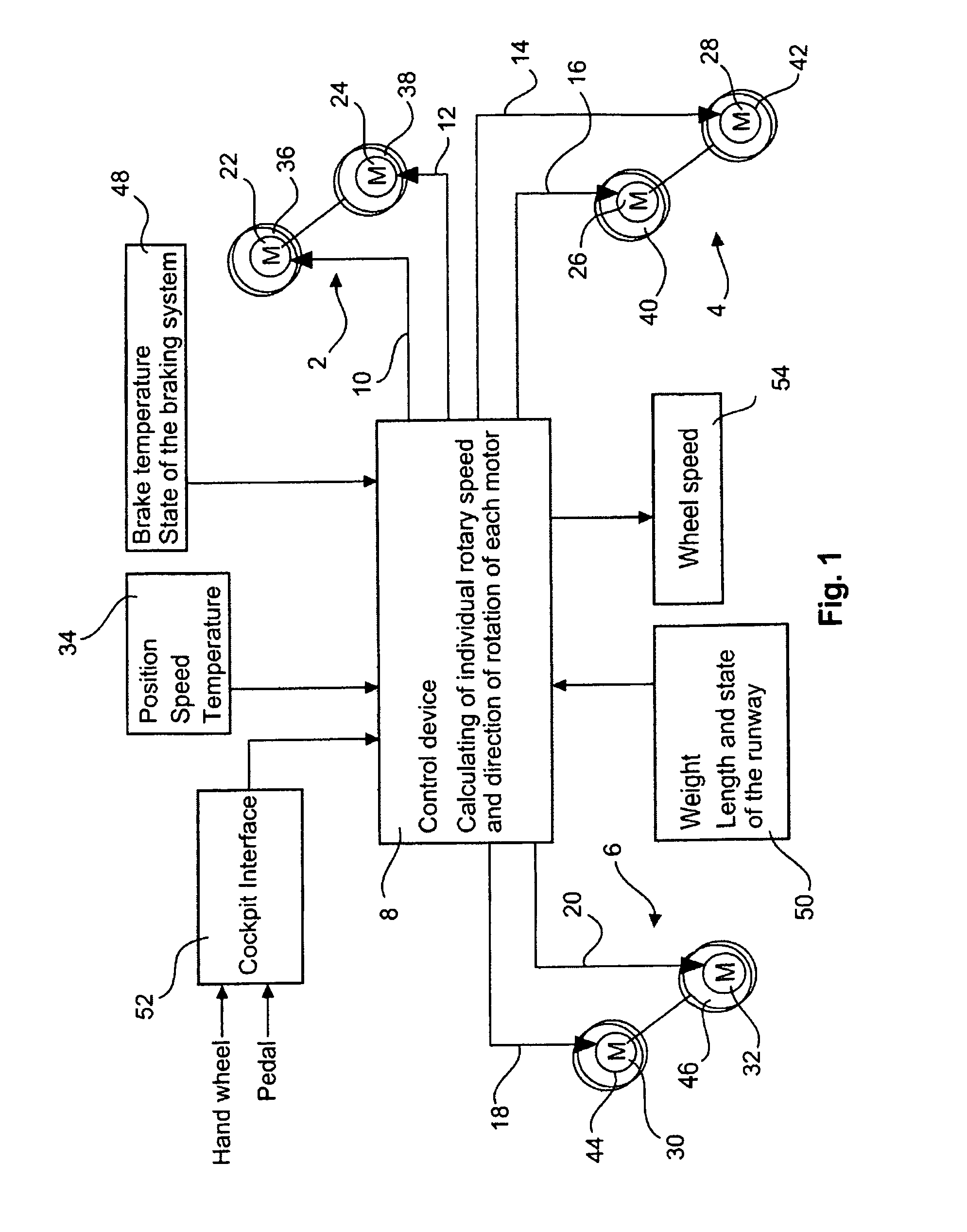
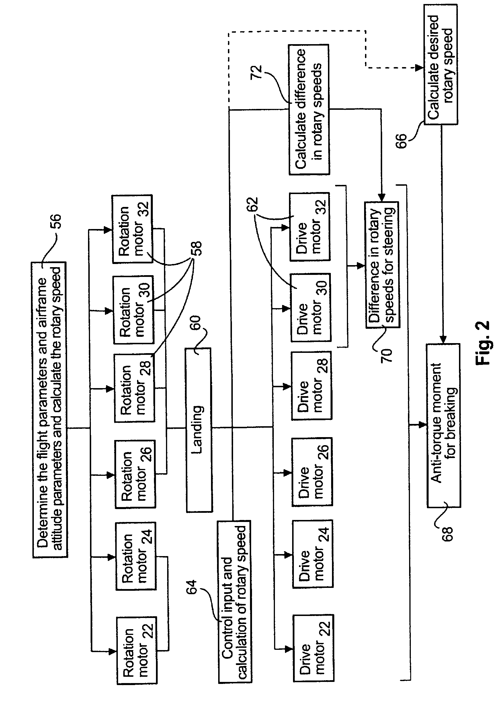
[0019]The following description of FIG. 1 refers to the exemplary embodiment of a passenger aircraft that comprises a main undercarriage that is arranged in the region of the wing root, as well as a steerable nosewheel gear. Since FIG. 1 explains the powered wheel system according to the invention in an exemplary manner with reference to an example, the main undercarriage 2 comprises a pair 2 of wheels that are arranged side by side (right-hand side of the aircraft) and a pair 4 of wheels (left-hand side of the aircraft), as well as a pair 6 of wheels on the nosewheel gear. Of course any further embodiments may be implemented in which larger numbers of wheels or pairs of wheels or undercarriages are provided.

[0020]The core piece of the powered wheel system according to the invention is a control device 8 which in order to carry out its specific tasks consumes data from other aircraft systems and is equipped to emit signals 10 to 20 to motors 22 to 32, which signals cause the respect...


PUM


Abstract

The invention relates to a powered wheel system for an aircraft, comprising at least one undercarriage with several rotatably held wheels, with the powered wheel system comprising two or more motors of which in each case at least one motor is coupled to at least one of the wheels, and comprising at least one control device that is coupled to the motors. A control device is equipped to control operation of the motors independently of each other as far as their respective rotary speeds and direction of rotation are concerned, so that the system is able, among other things, to effect taxiing; by means of rotary speed differentials on different motors to be able to steer the aircraft; prior to landing to bring the wheel circumference speeds to landing speed; and to boost the undercarriage brakes of the aircraft. Furthermore, by means of an improvement of the system according to the invention, the rotary speeds of the wheels may be determined with precision. The invention furthermore relates to a method for driving wheels of an aircraft.

Description

CROSS-REFERENCE TO RELATED APPLICATIONS[0001]This application claims the benefit of the filing date of U.S. Provisional Patent Application No. 61 / 067,586 filed Feb. 29, 2008, the disclosure of which is hereby incorporated herein by reference.[0002]The invention relates to a powered wheel system for an aircraft, and to a method for driving wheels of an aircraft.BACKGROUND OF THE INVENTION[0003]Aircraft, and in particular aircraft that are not capable of vertical takeoff and landing, comprise undercarriages comprising several wheels. Normally, the wheels of such undercarriages are not actively driven nor are they made to rotate during the landing procedure, prior to the landing shock. However, there are printed prior art publications in which it has been proposed that wheels of undercarriages be driven so that, in particular, tyre wear as a result of friction during landing is minimised, and / or that the aircraft can be taxied. For example, WO 2006 / 078322 A2 describes a drive system fo...

Claims


Application Information

Patent Timeline
Patent Type & Authority Patents(United States)
IPC IPC(8): B64C25/50
CPCB64C25/405B64C25/50Y02T50/823Y02T50/80
Inventor DILMAGHANI, HOMAYOUNBOHLEN, CARSTEN
Owner AIRBUS SAS
Why Eureka
Try Eureka